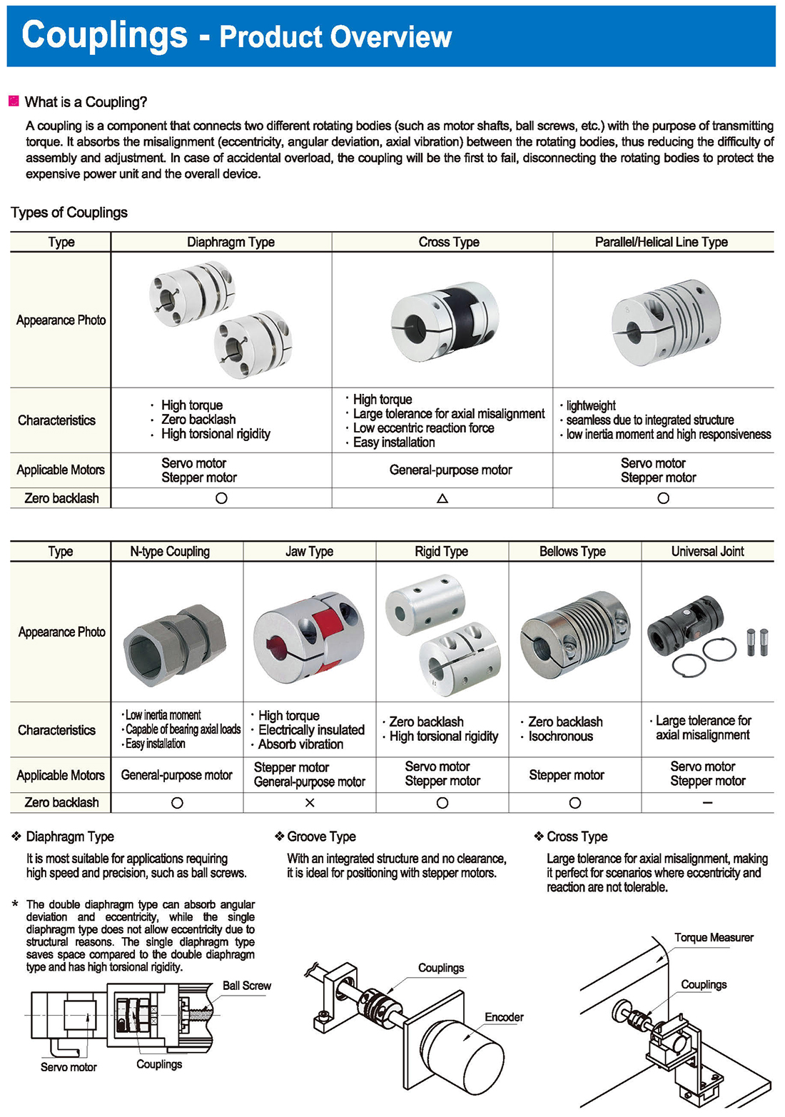
Tipi di raccordi
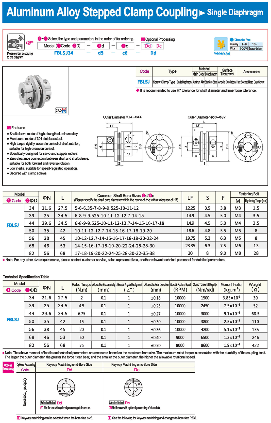
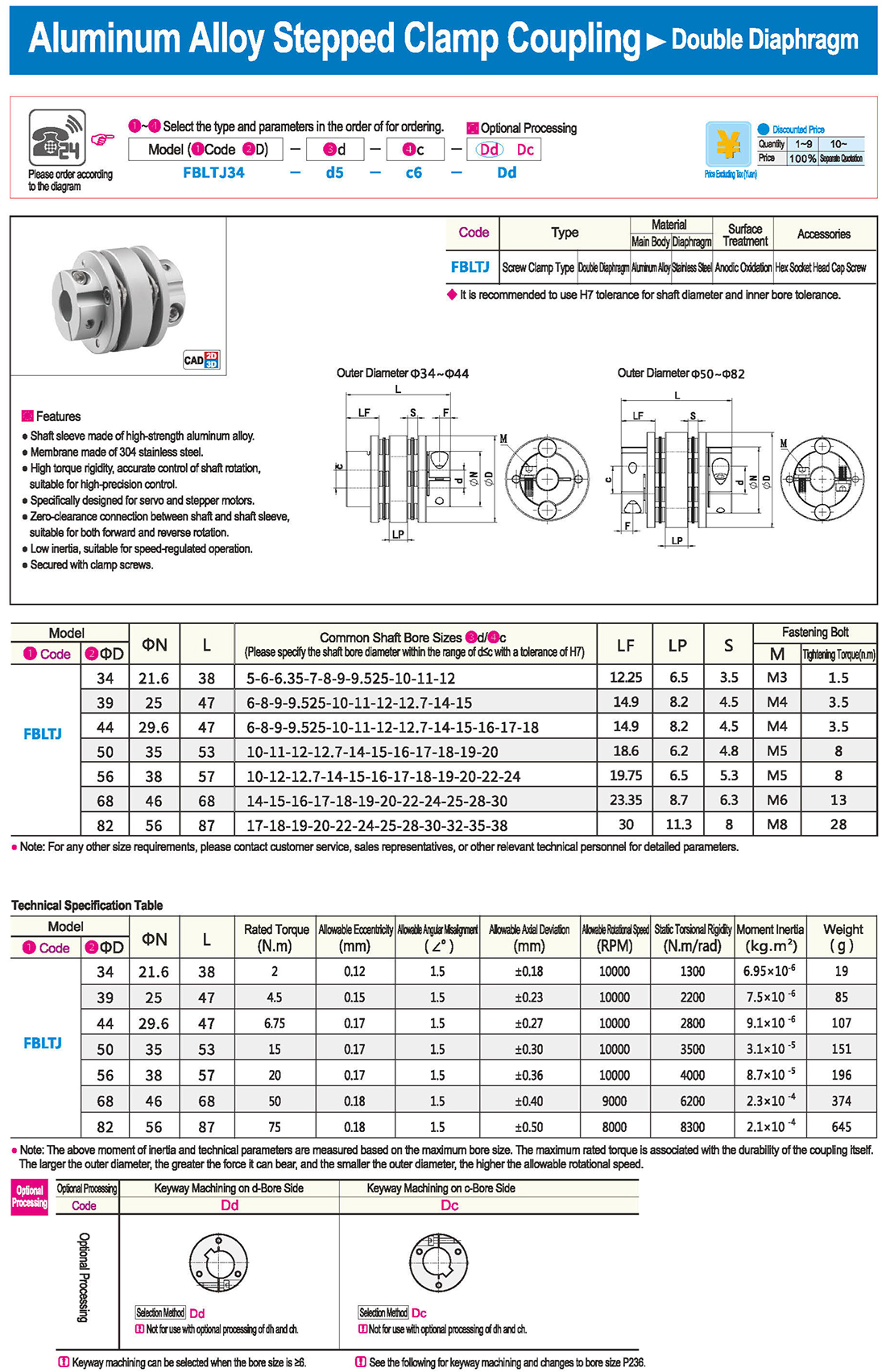
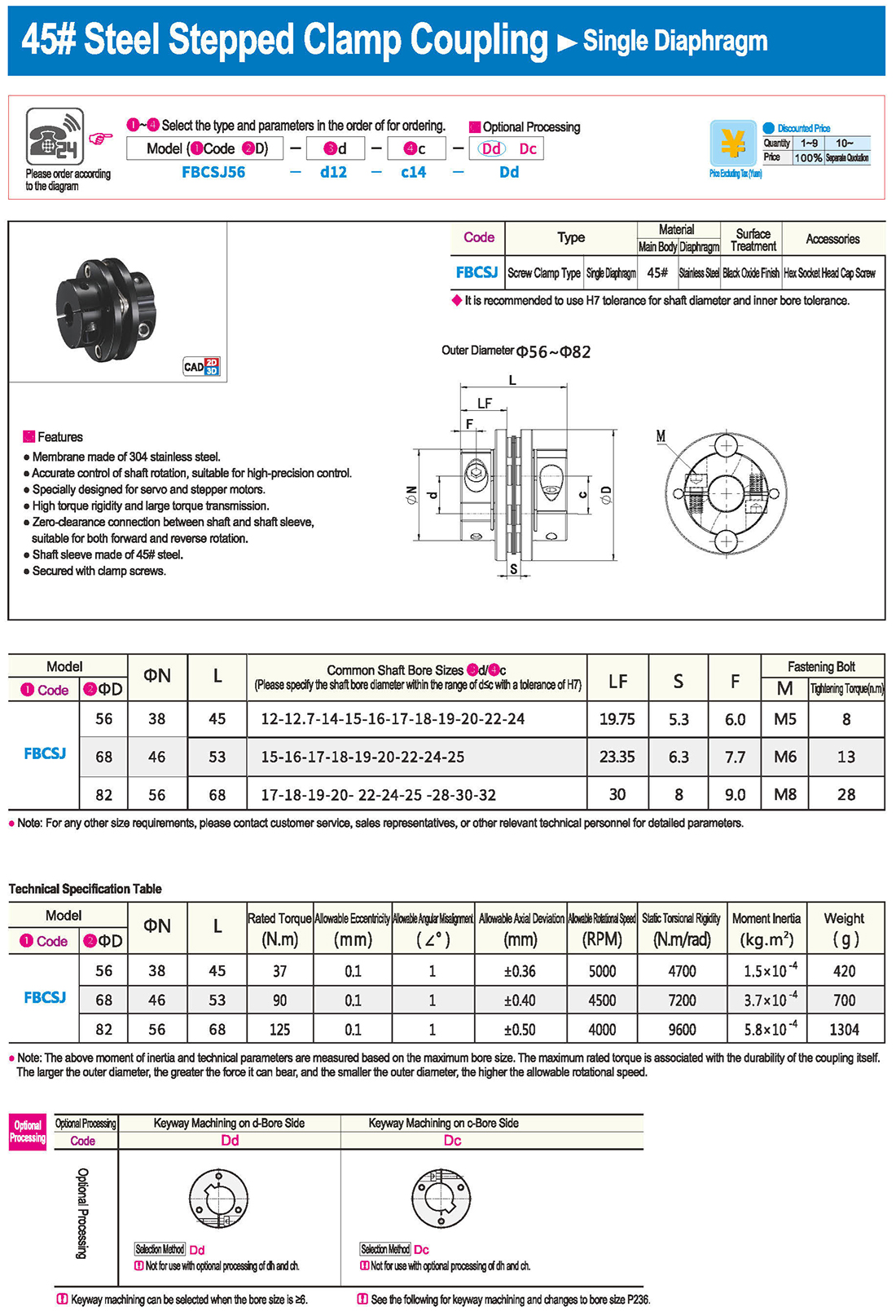
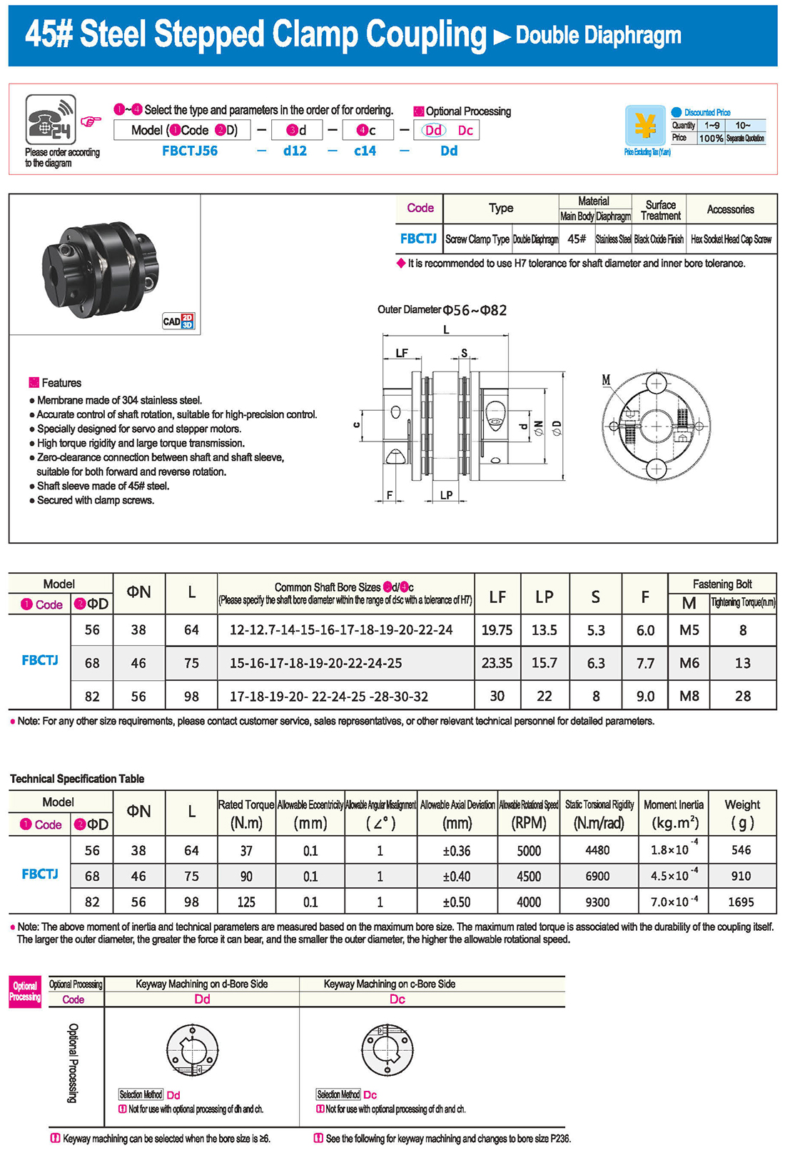
Tipo: tipo a diaframma, tipo a croce, tipo a linea parallela/elicoidale
È più adatto ad applicazioni che richiedono alta velocità e precisione, come le viti a sfera.
Groove tipo
Con una struttura integrata e senza spazi liberi, è ideale posizionarsi con i motori stepper.
Grande tolleranza per il disallineamento assiale, che lo rende perfetto per scenari in cui l’eccentricità e la reazione non sono tollerabili.
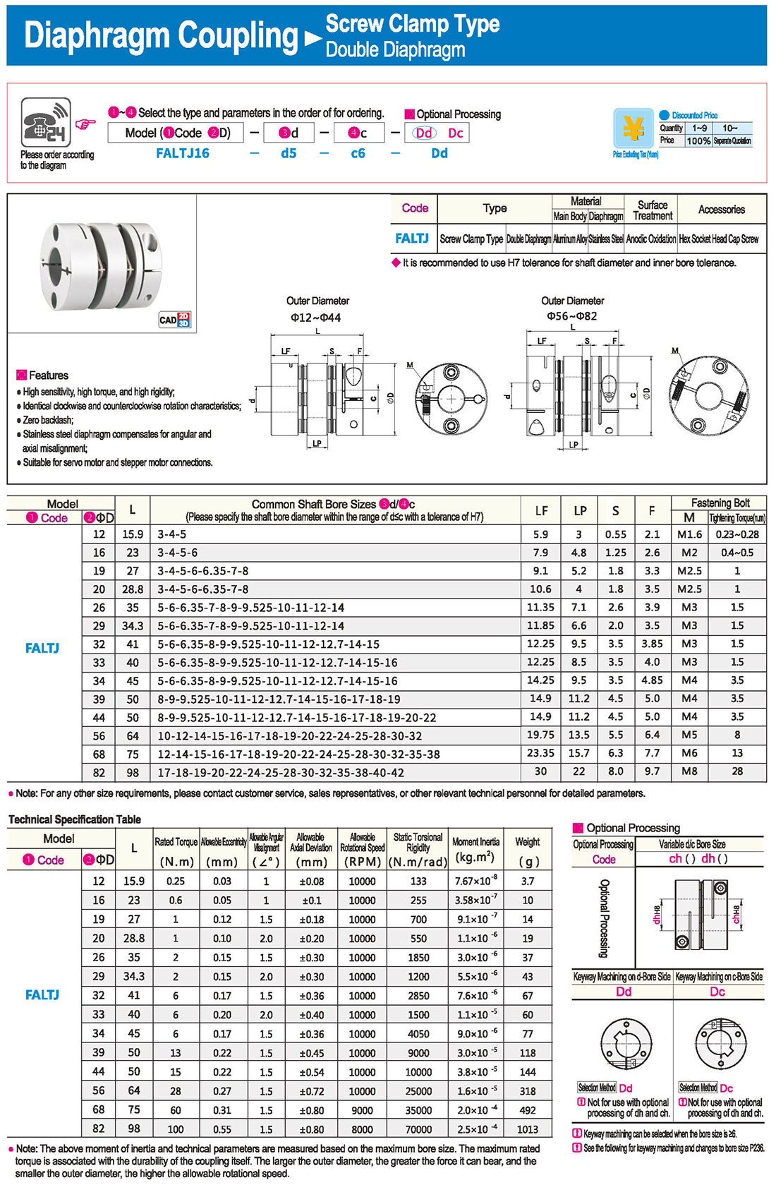
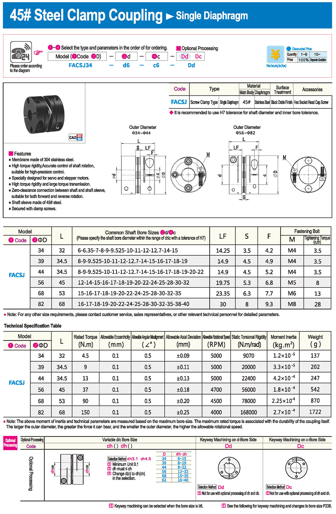
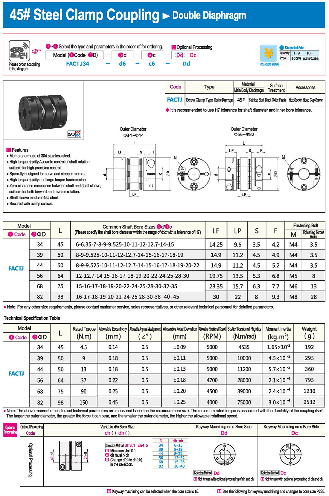
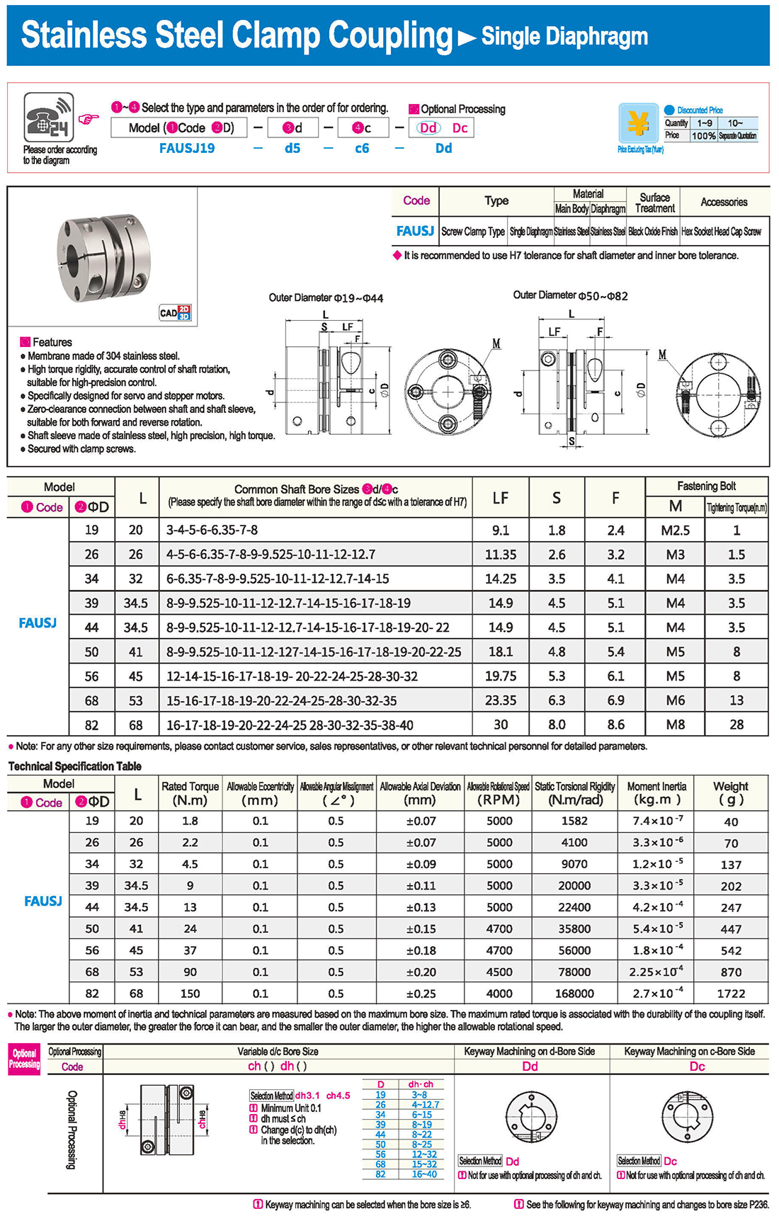
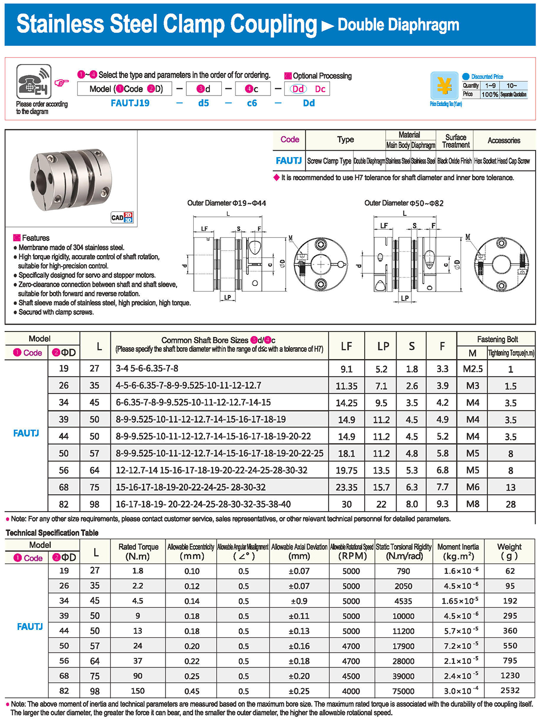
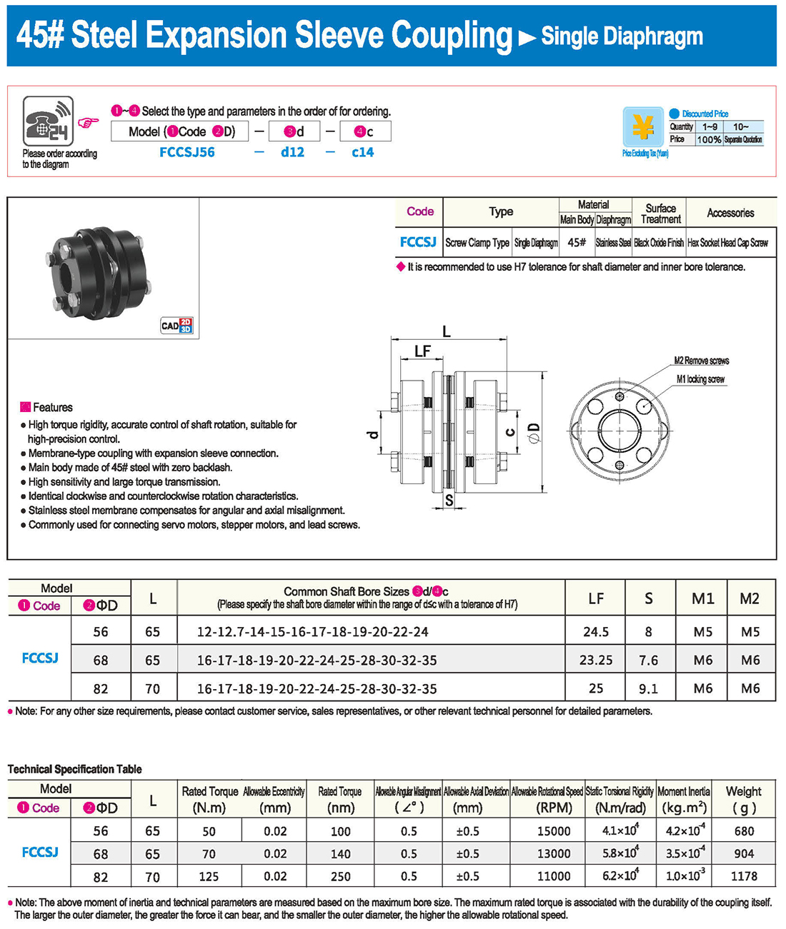
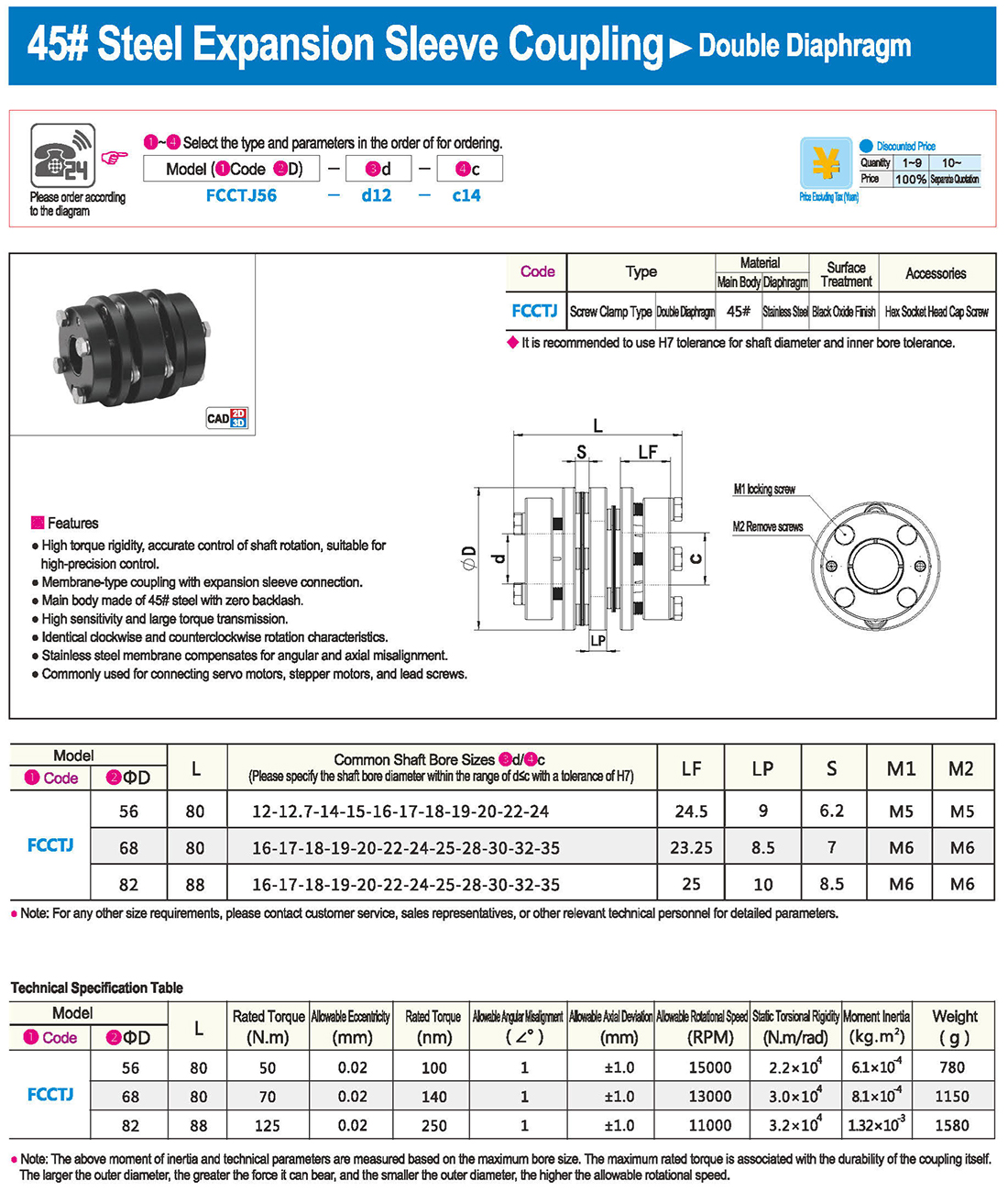
* il tipo a diaframma doppio può assorbire deviazione angolare ed eccentricità, mentre il tipo a diaframma singolo non consente eccentricità per ragioni strutturali. Il tipo a diaframma singolo consente di risparmiare spazio rispetto al tipo a diaframma doppio e presenta una forte rigidità torsionale.
& codificatore Misuratore della coppia
Per selezionare il motore, scegliere il tipo di accoppiamento appropriato in base al tipo e all’applicazione del motore.
* le combinazioni di tipi di motore e tipi di attacco non si limitano a quelli indicati di seguito. Fare riferimento alle singole pagine del prodotto prima di effettuare una selezione.
* quando si seleziona in base alla coppia, iniziare dal passo 2.
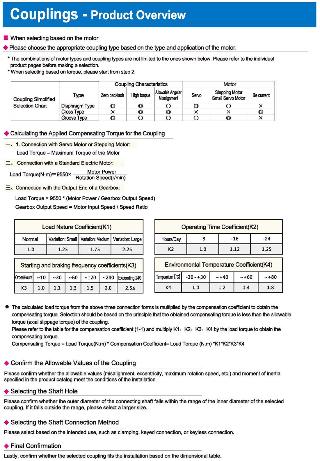
Coupling Simplified Selection Chart
Diaphragm Type Coupling Characteristics Allowable Angular Misalignment Motor Stepping Motor, Small Servo Motor
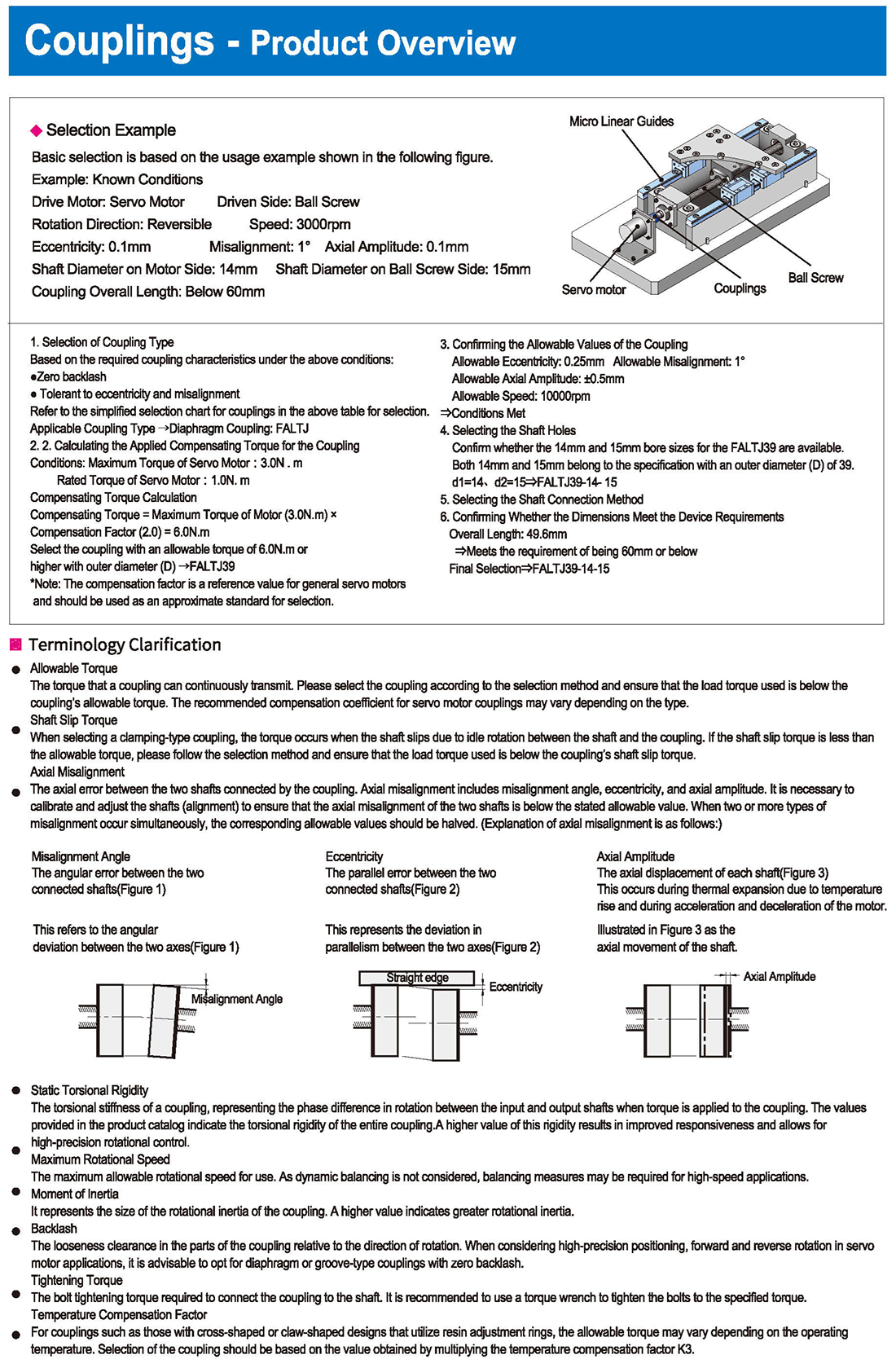
Calculating the Applied Compensating Torque for the Coupling
1. Connection with Servo Motor or Stepping Motor: Load Torque = Maximum Torque of the Motor
2. Connection with a Standard Electric Motor: Load Torque, Motor Power, Rotation Speed
3. Connection with the Output End of a Gearbox:
Load Torque = 9550 * (Motor Power / Gearbox Output Speed) Gearbox Output Speed = Motor Input Speed / Speed Ratio
Load Nature Coefficient, Operating Time Coefficient, Environmental Temperature Coefficient
Normal, Variation: Small, Medium, Large, Hours/Time, Exceeding, Temperature
The calculated load torque from the above three connection forms is multiplied by the compensation coefficient to obtain the compensating torque. Selection should be based on the principle that the obtained compensating torque is less than the allowable torque (axial slippage torque) of the coupling.
Please refer to the table for the compensation coefficient and multiply K4 by the load torque to obtain the compensating torque.
Compensating Torque = Load Torque * Compensation Coefficient = Load Torque
Confirm the Allowable Values of the Coupling
Please confirm whether the allowable values (misalignment, eccentricity, maximum rotation speed, etc.) and moment of inertia specified in the product catalog meet the conditions of the installation.
Selecting the Shaft Hole
Please confirm whether the outer diameter of the connecting shaft falls within the range of the inner diameter of the selected coupling. If it falls outside the range, please select a larger size.
Selecting the Shaft Connection Method
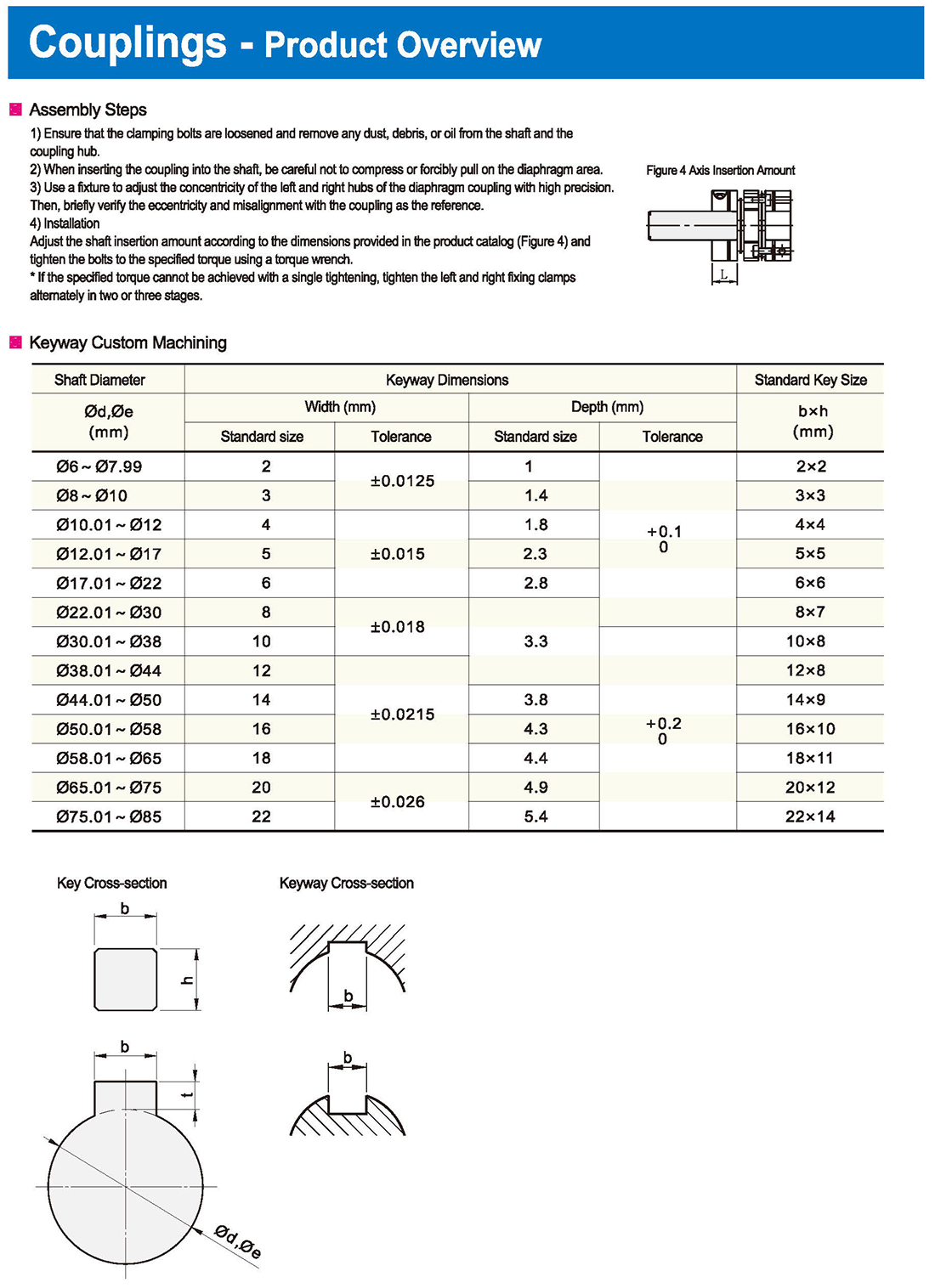
Please select based on the intended use, such as clamping, keyed connection, or keyless connection.
Final Confirmation
Lastly, confirm whether the selected coupling fits the installation based on the dimensional table.


 inglese
 russo
russo spagnolo
 italiano
 arabo
arabo coreano
 tedesco
 giapponese
 vietnamita
 turco
turco
 introduzione
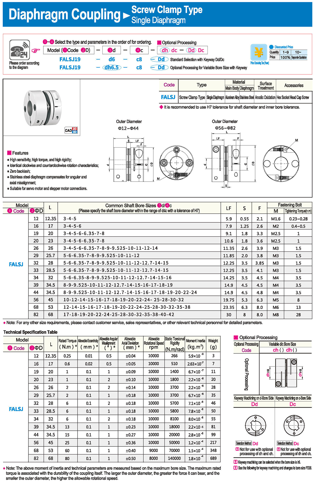
 Tabella specifica
 scarica


