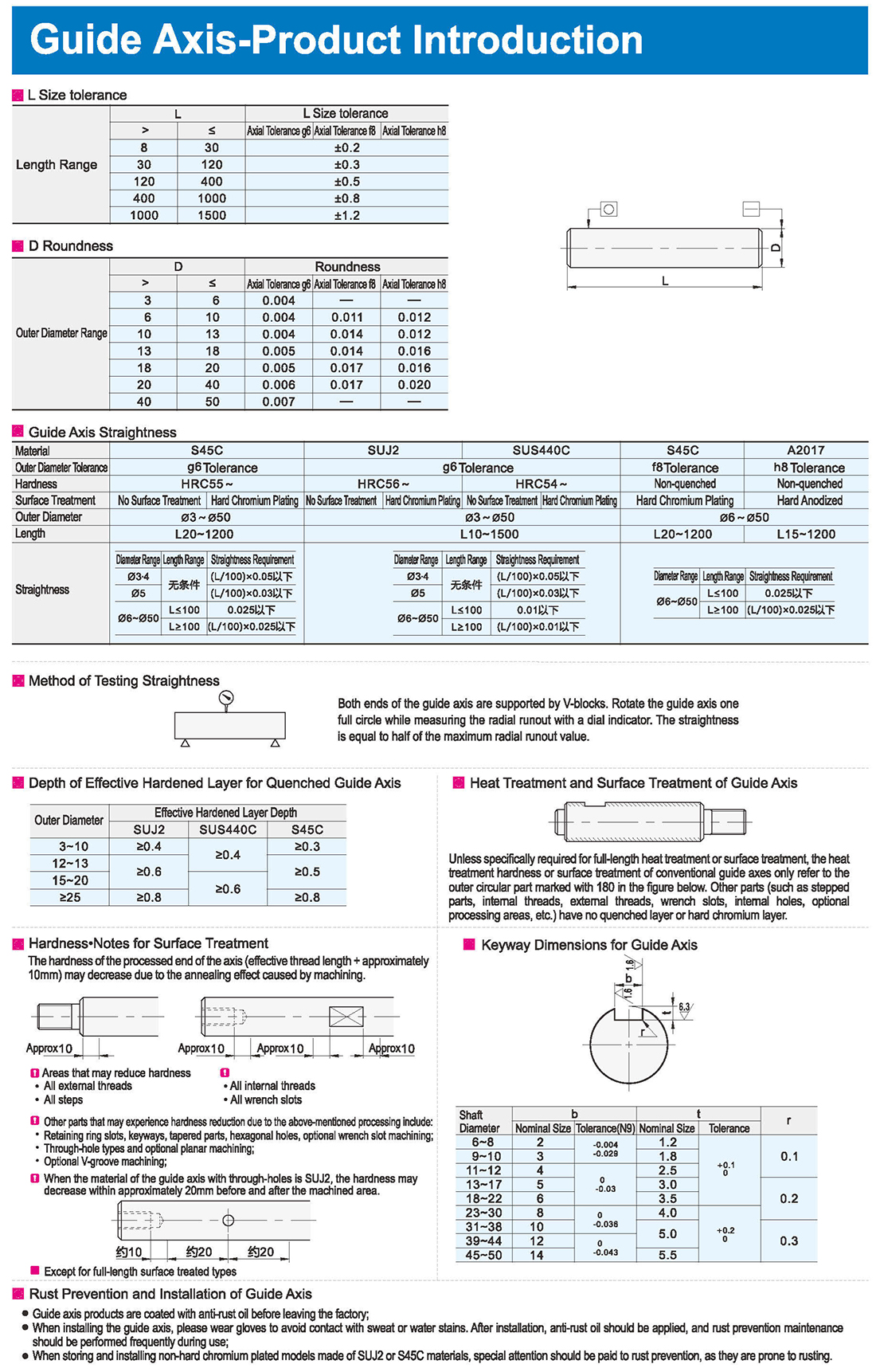
1. Profondità dello strato indurito efficace per l’asse di guida temprato
2. Trattamento termico e trattamento superficiale dell’asse guida.
Salvo se specificamente richiesto per il trattamento termico su tutta la lunghezza o per il trattamento di superficie, la durezza del trattamento termico o il trattamento di superficie degli assi guida convenzionali si riferiscono unicamente alla parte circolare esterna contrassegnata con 180 nella figura seguente. Altre parti (quali le parti scalate, le filettature interne, le filettature esterne, le fessure a chiave, i fori interni, le aree facoltative di lavorazione, ecc.) non hanno uno strato temprato o di cromo duro.
3. Prevenzione della ruggine e installazione di assi guida
I prodotti dell’asse guida sono ricoperti di olio antiruggine prima di lasciare lo stabilimento;
Quando si installa l’asse guida, indossare guanti per evitare il contatto con macchie di sudore o acqua. Dopo l’installazione, si dovrebbe applicare olio antiruggine e la manutenzione della prevenzione della ruggine dovrebbe essere effettuata frequentemente durante l’uso;
Quando si immagazzinano e si installano modelli placcati di cromo non duro costruiti con materiali SUJ2 o S45C, si dovrebbe prestare particolare attenzione alla prevenzione della ruggine, in quanto sono soggetti a corrosione.
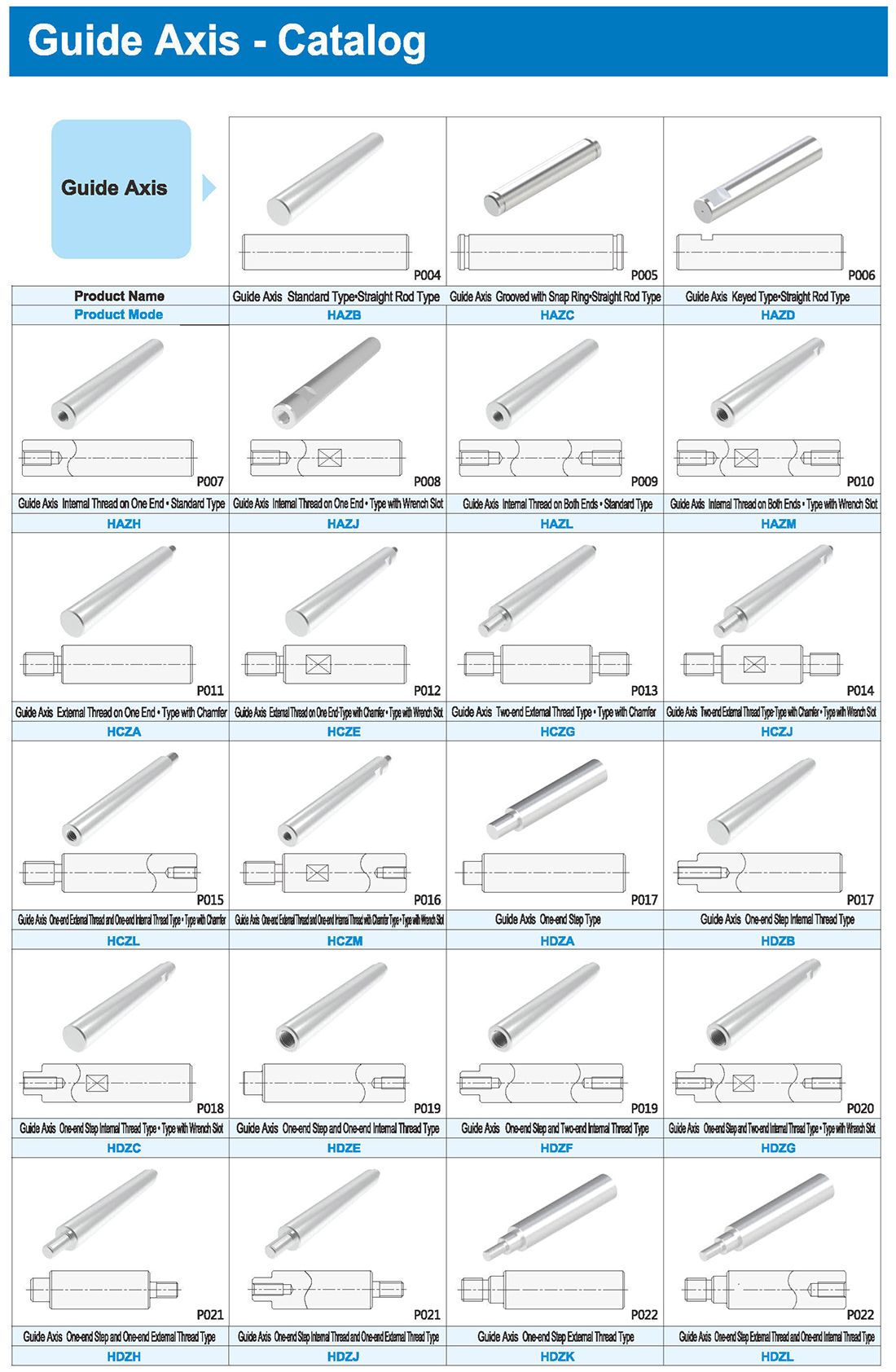
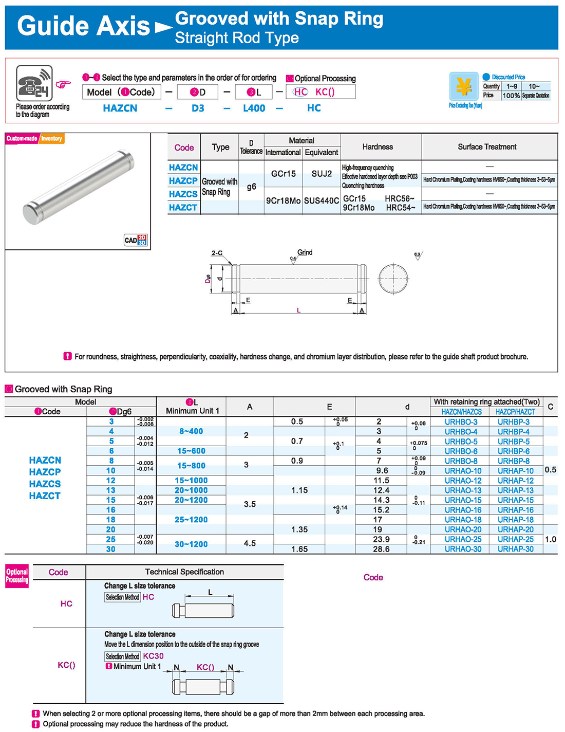
1.Grooved with Snap Ring
Cancel snap ring groove on one end Move the L dimension position to the outside of the snap ring groove
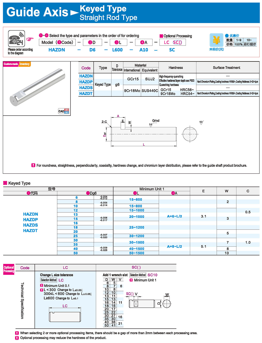
2.Keyed Type Internal Thread on One End
Precision Grade Ordinary Grade Precision Grade
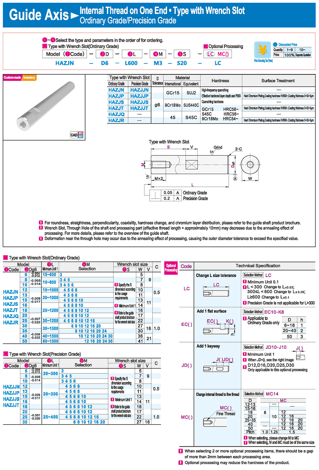
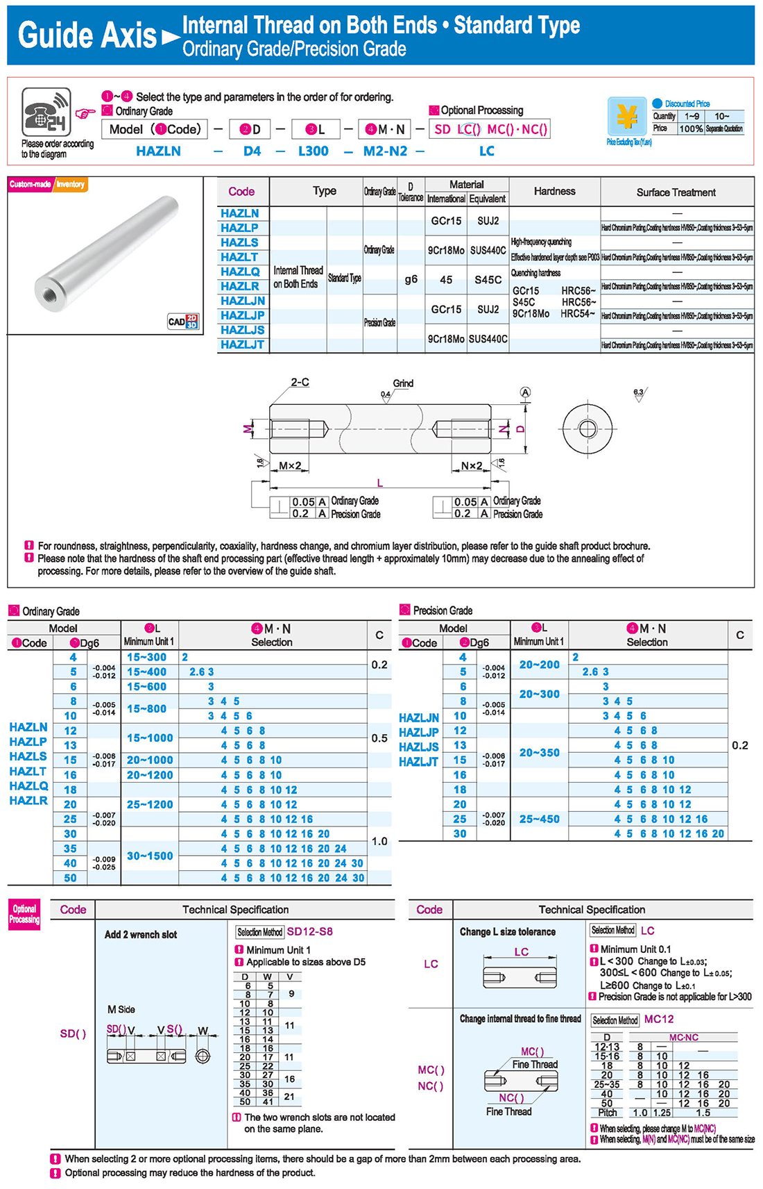
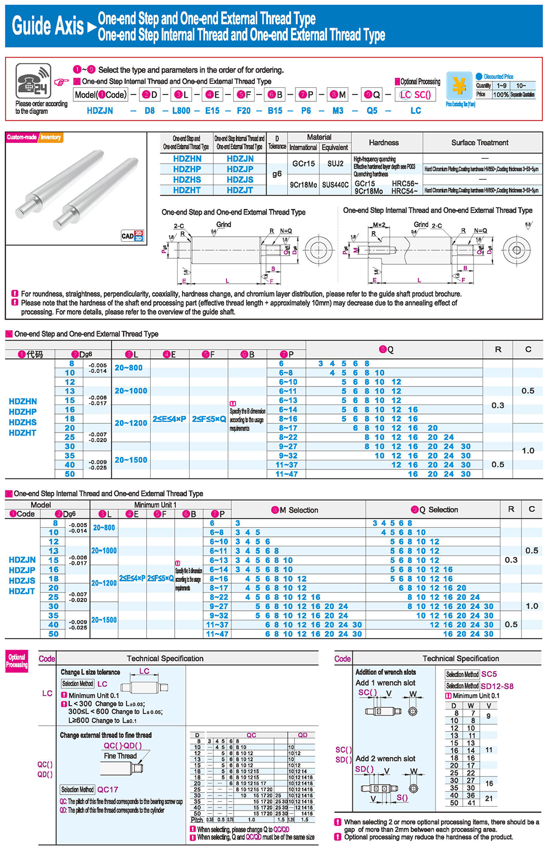
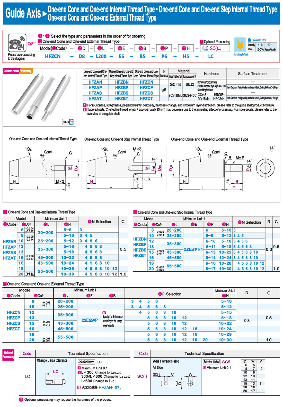
Please note that the hardness of the shaft end processing part (effective thread length + approximately 10mm) may decrease due to the annealing effect of processing. For more details, please refer to the overview of the guide shaft.
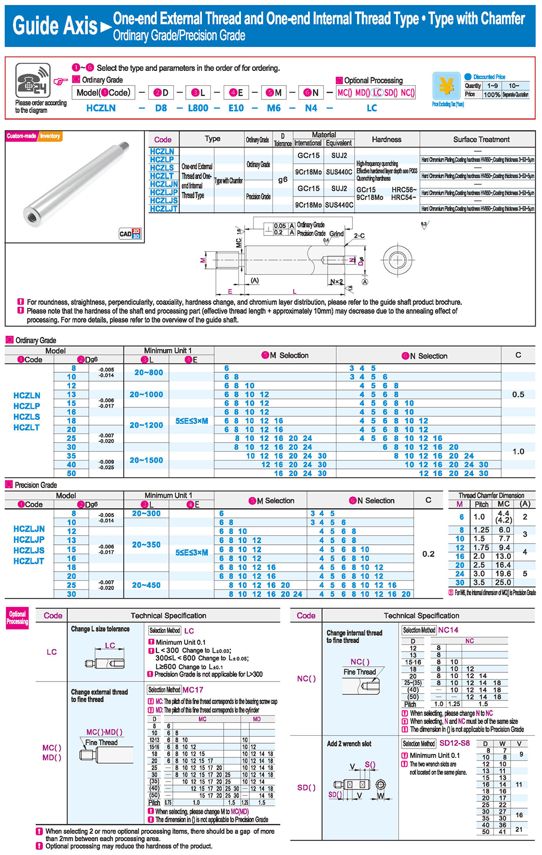
Selection: Precision Grade is not applicable for L>300
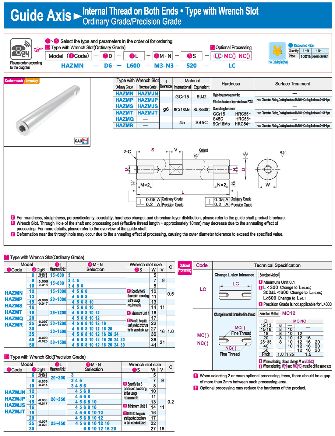
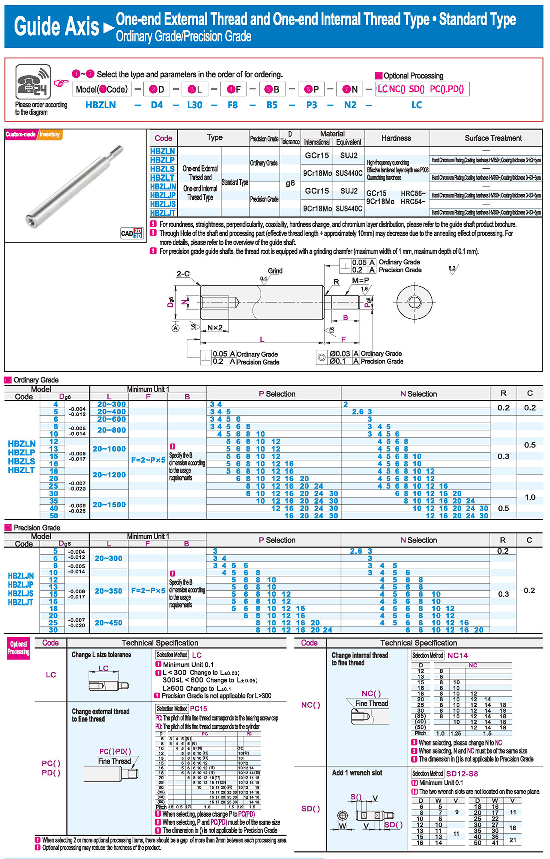
Change internal thread to fine thread Pitch Fine Thread
When selecting, please change M to MC
M and MC must be of the same size
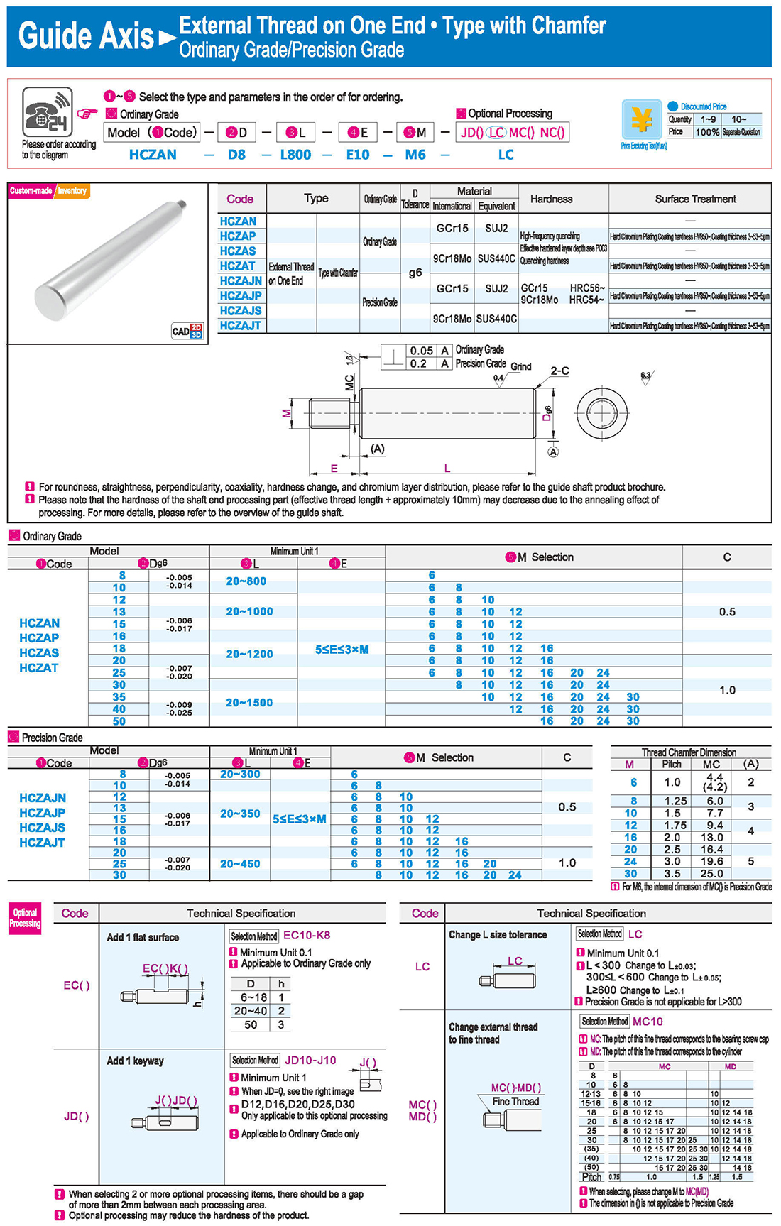
Applicable to Ordinary Grade only
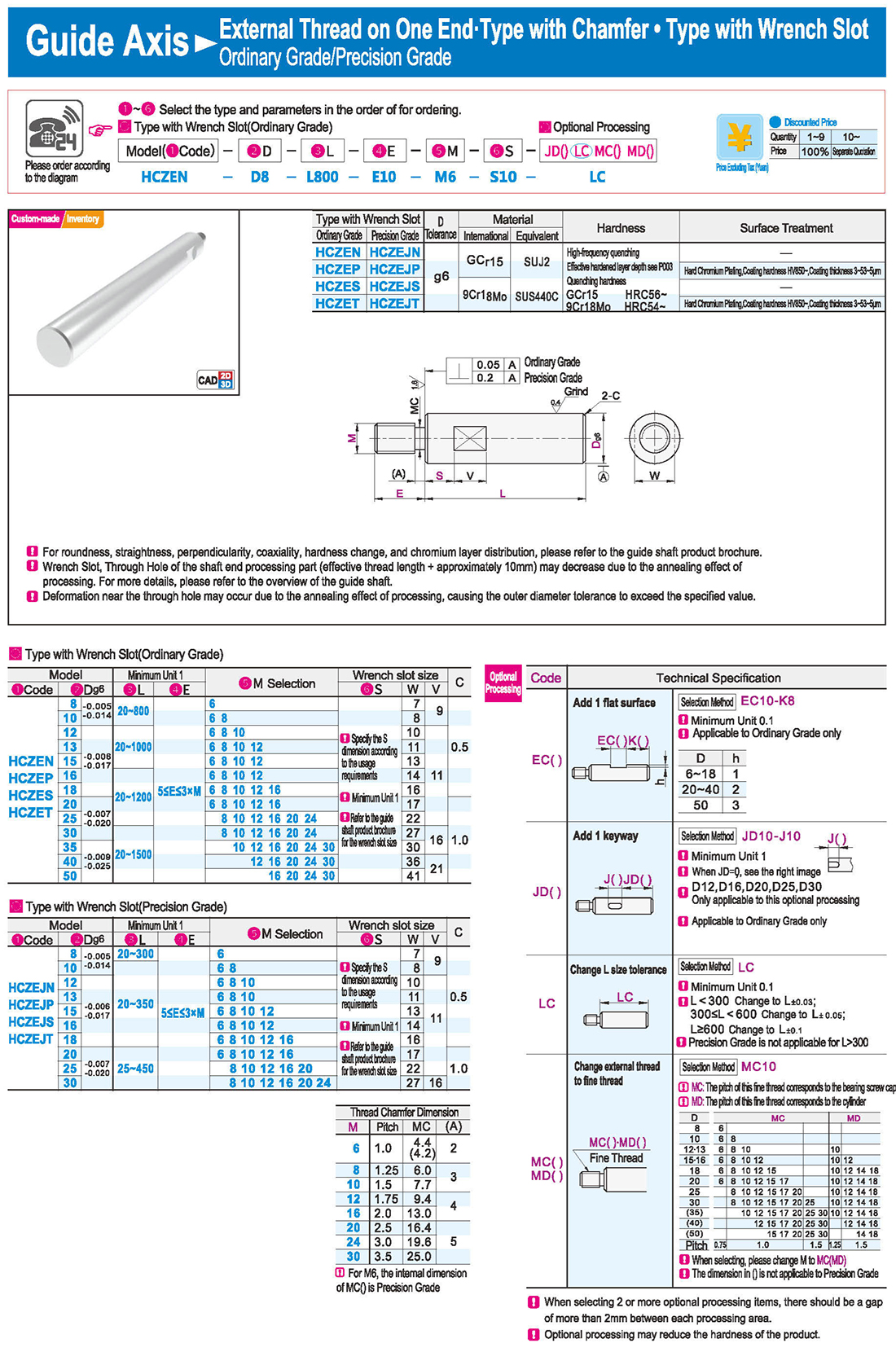
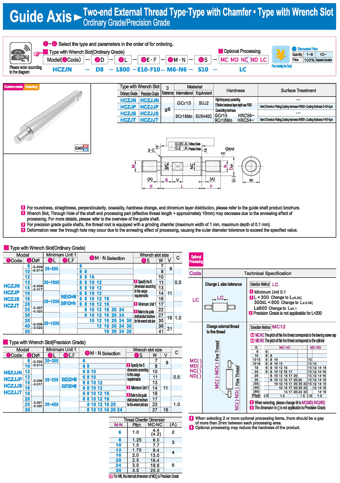
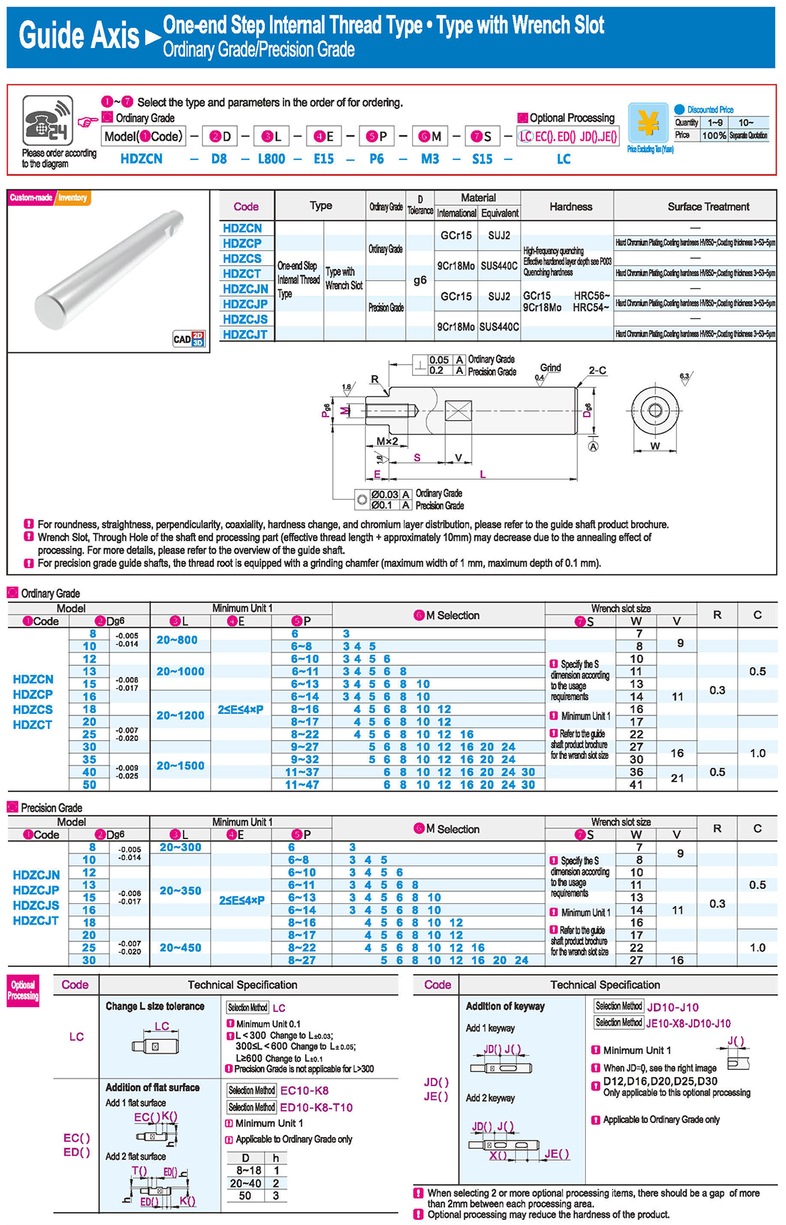
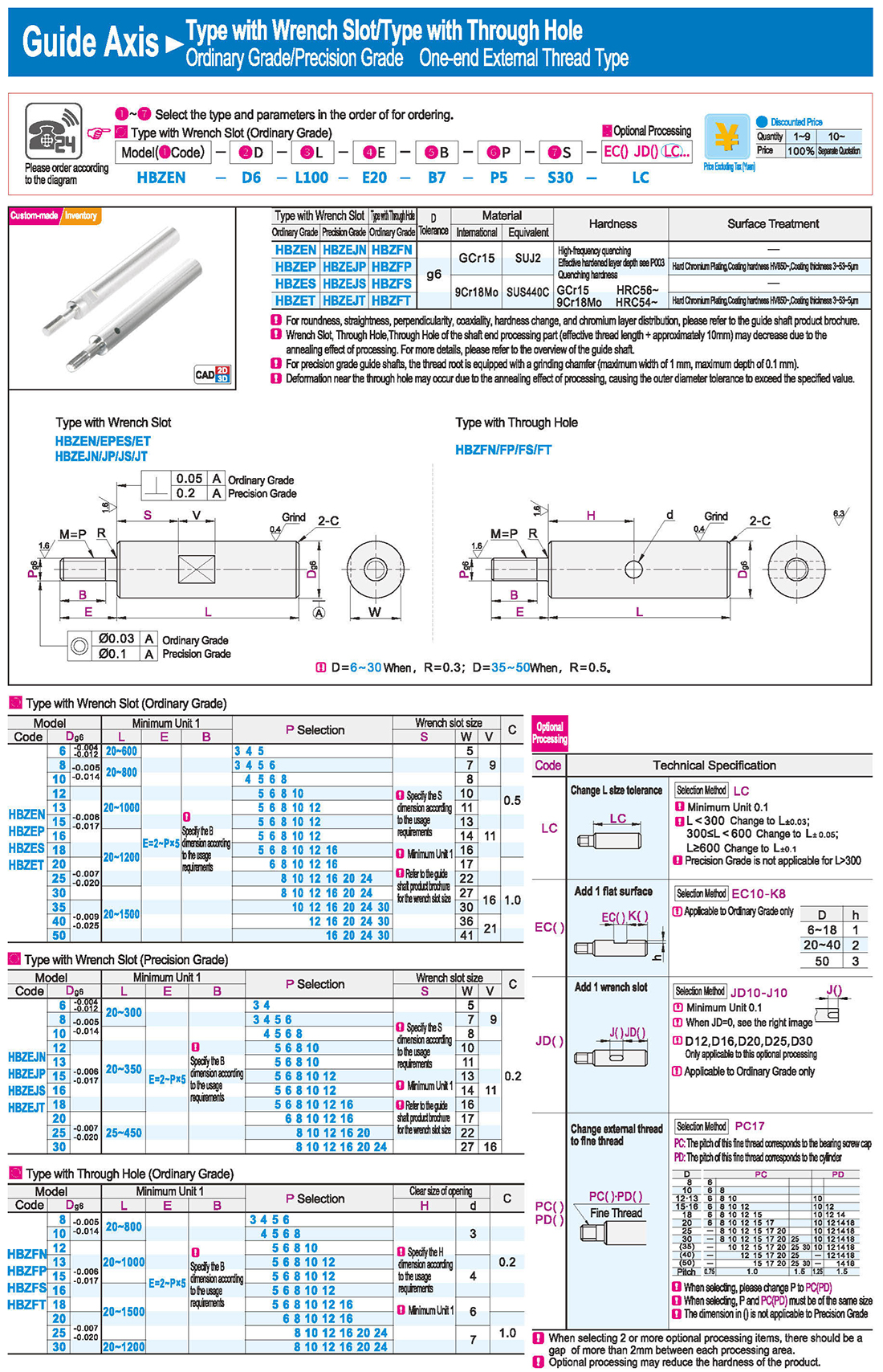
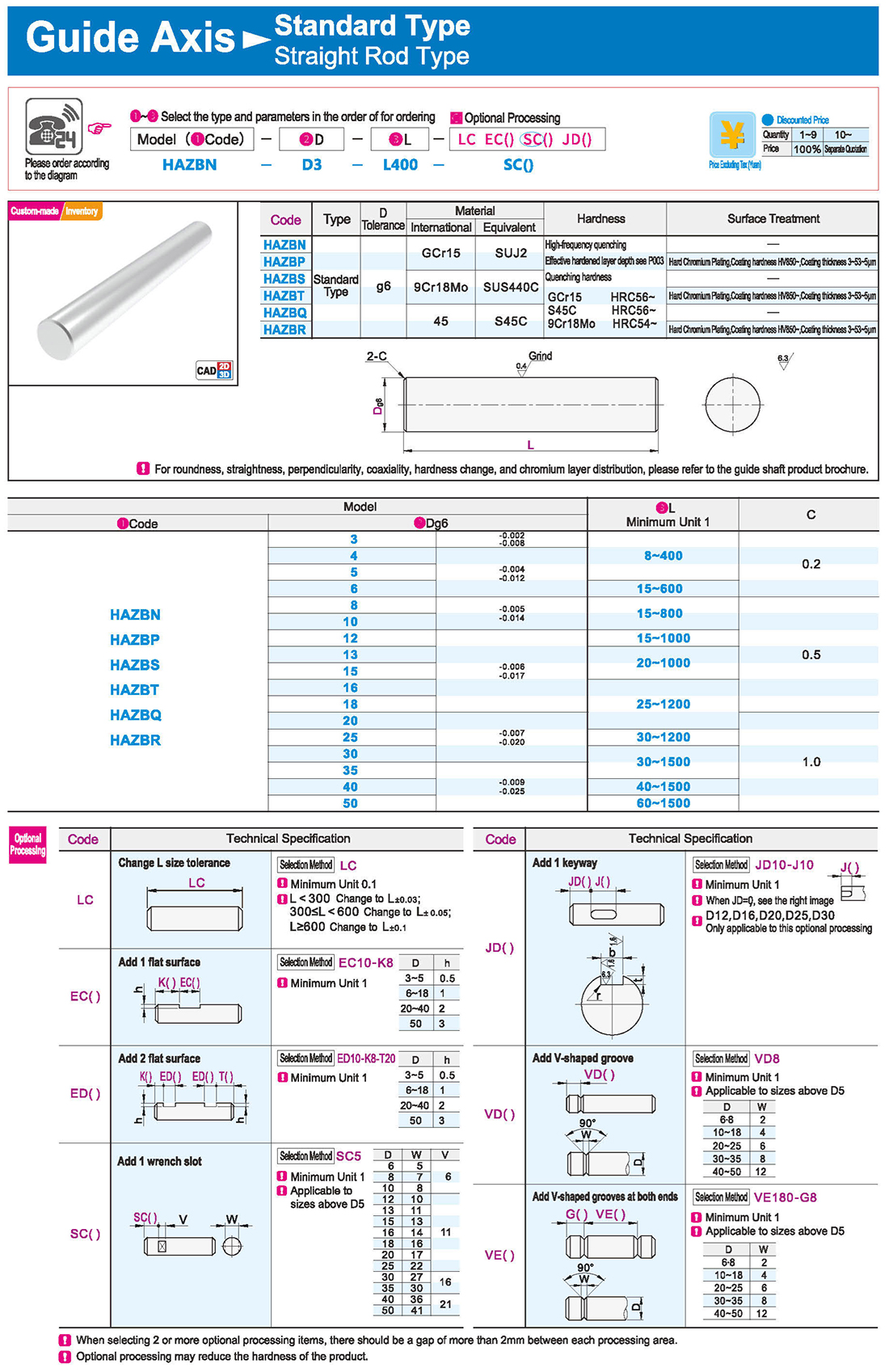
3.Type with Wrench Slot
Deformation near the through hole may occur due to the annealing effect of processing, causing the outer diameter tolerance to exceed the specified value.
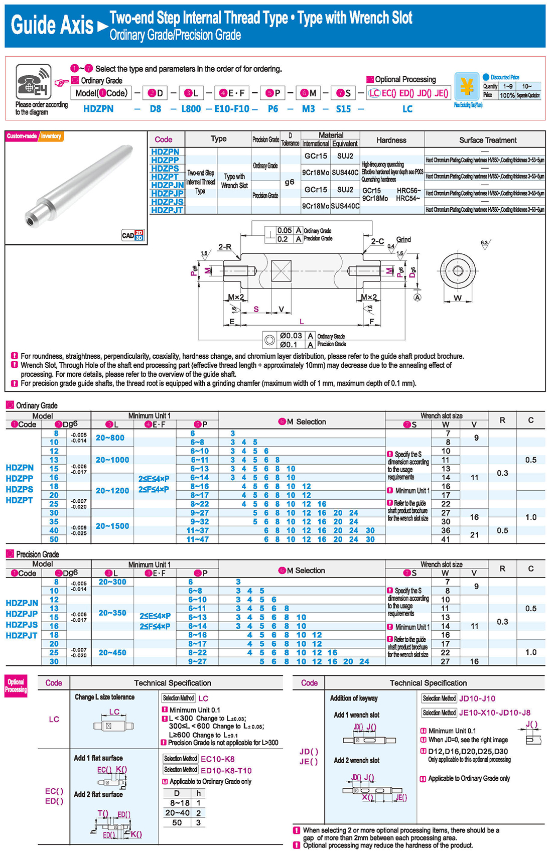
Specify the S dimension according to the usage requirements
Refer to the guide shaft product brochure for the wrench slot size
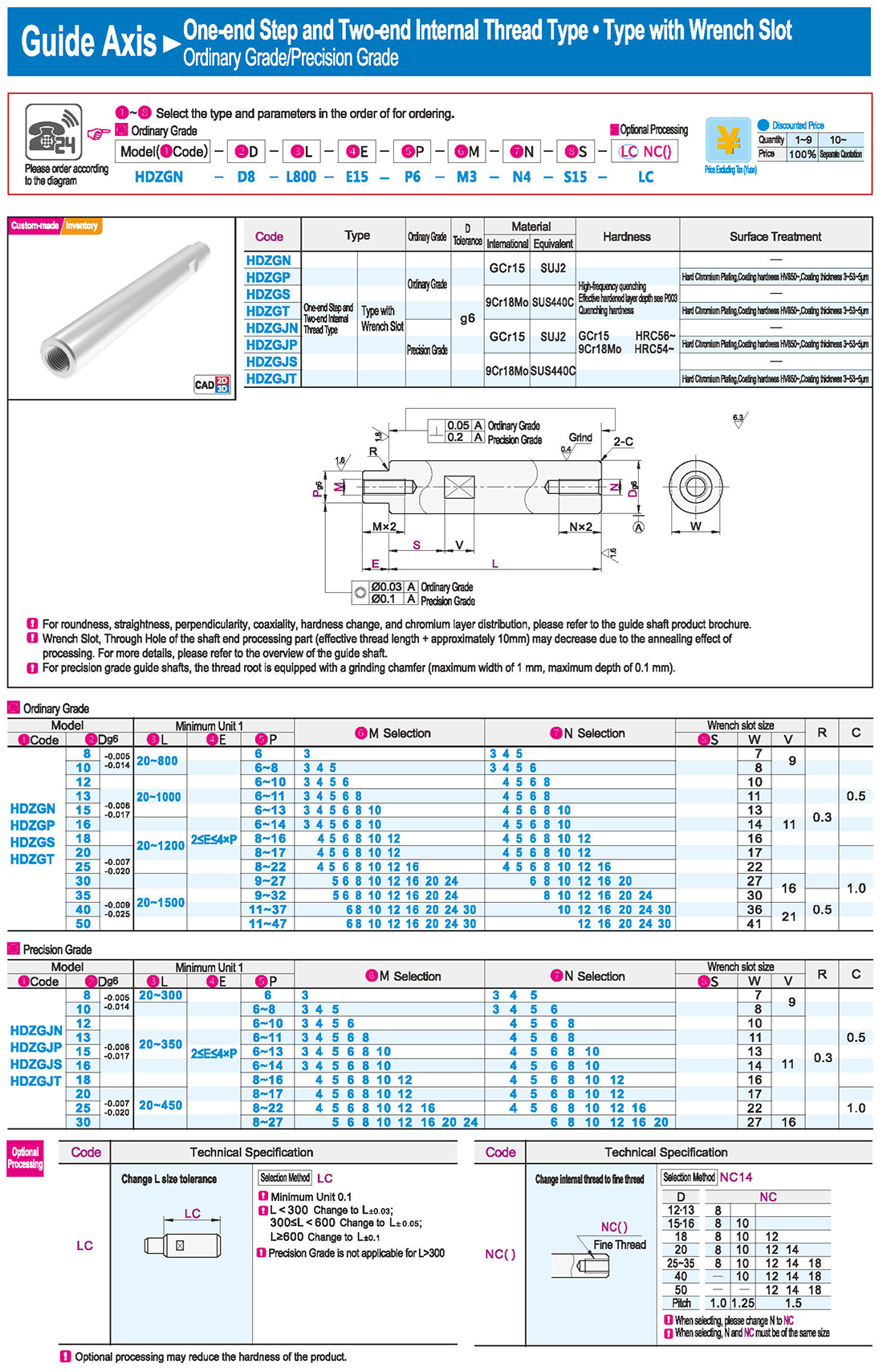
4.Internal Thread on Both Ends
The two wrench slots are not located on the same plane.
5.External Thread on One End · Type with Chamfer
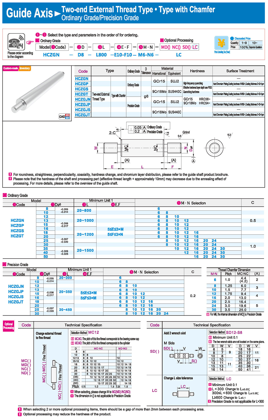
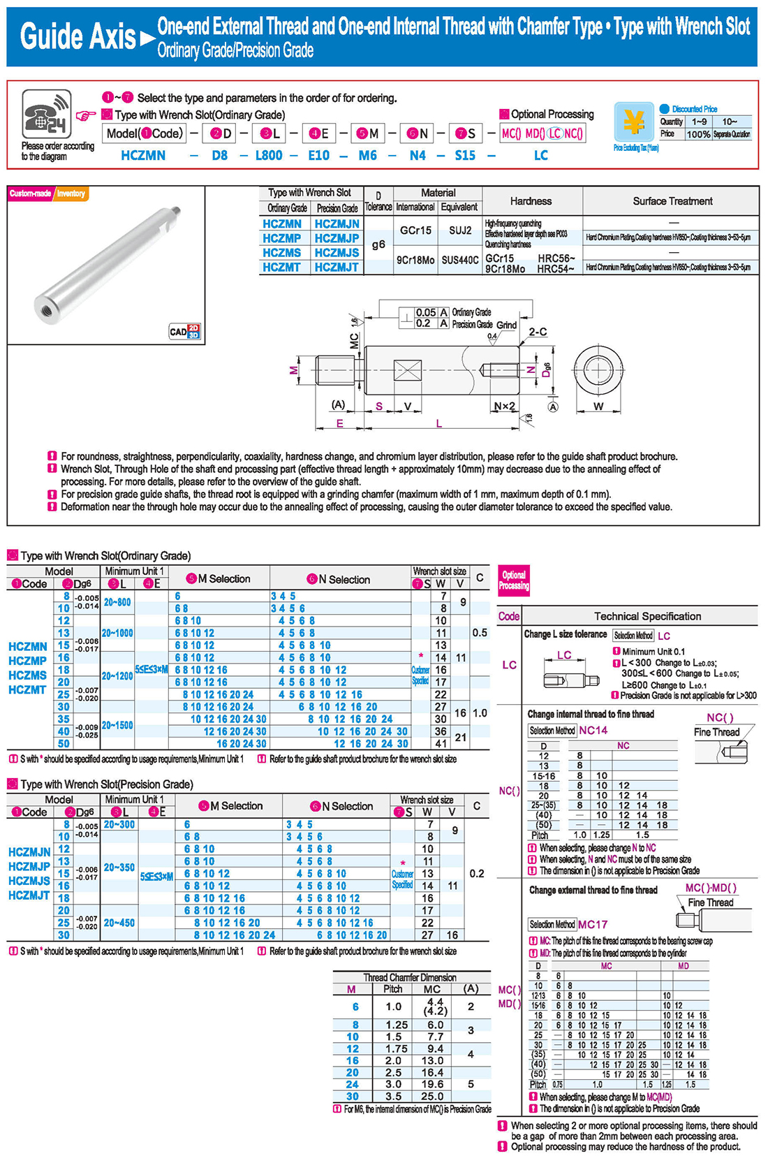
Thread Chamfer Dimension
For M6, the internal dimension of MC() is Precision Grade
MC: The pitch of this fine thread corresponds to the bearing screw cap
MD: The pitch of this fine thread corresponds to the cylinder
The dimension in () is not applicable to Precision Grade
6.One-end External Thread and One-end Internal Thread with Chamfer Type
Customer Specified
S with * should be specified according to usage requirements
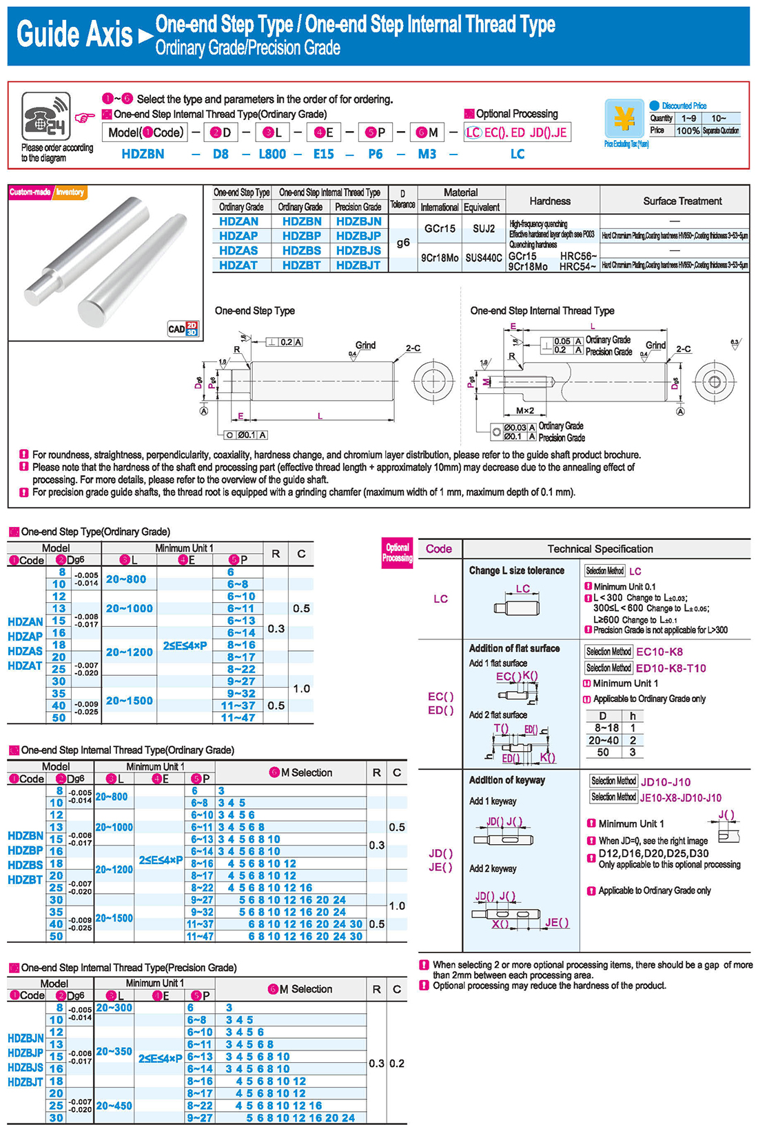
7.One-end Step Type / One-end Step Internal Thread Type
One-end Step Type / One-end Step Internal Thread Type
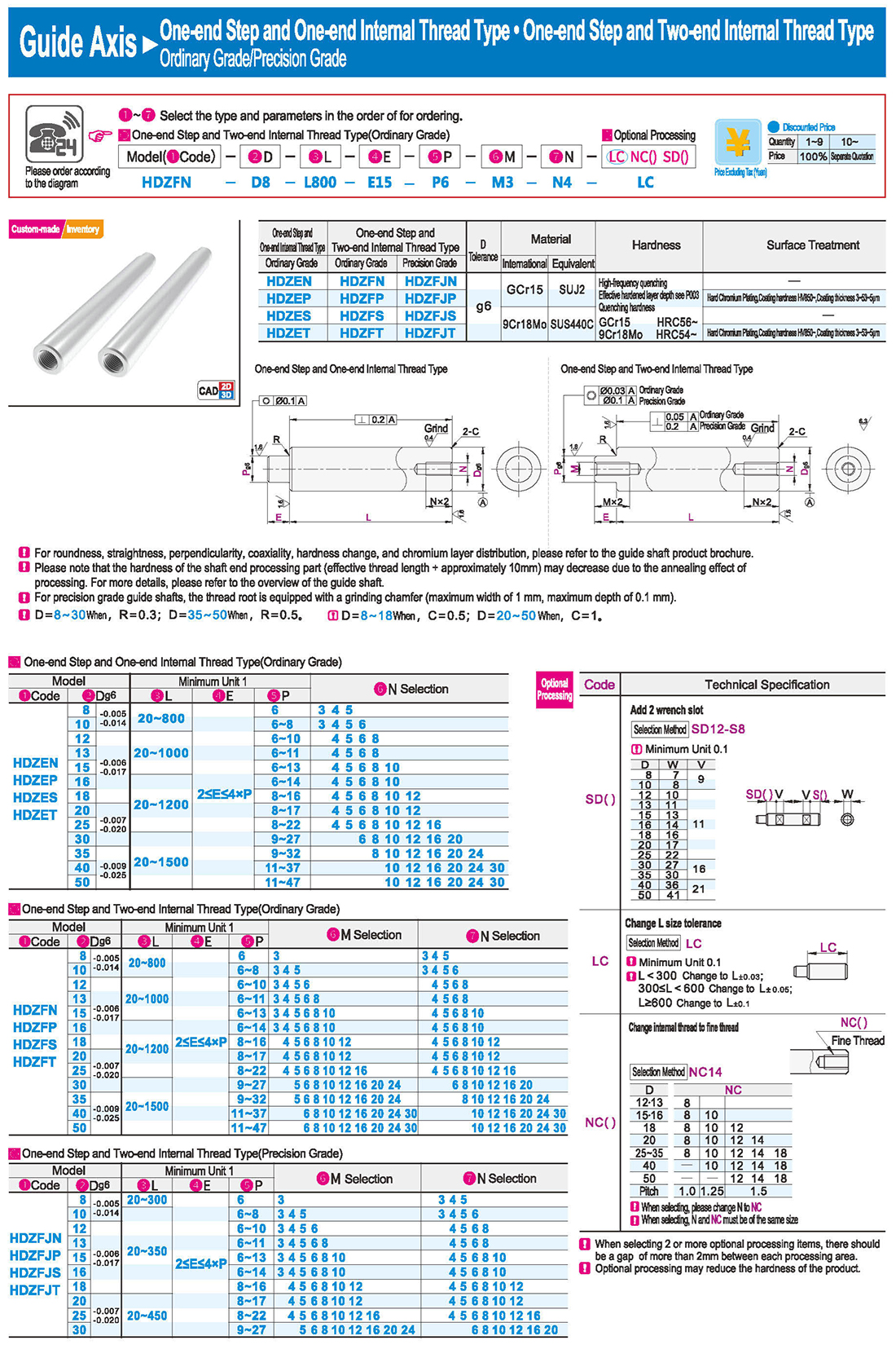
One-end Step and One-end Internal Thread Type · One-end Step and Two-end Internal Thread Type
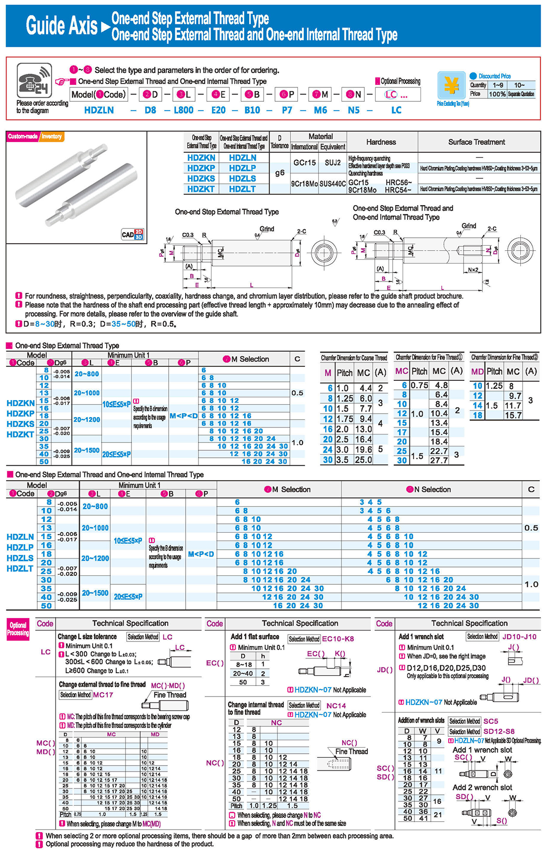
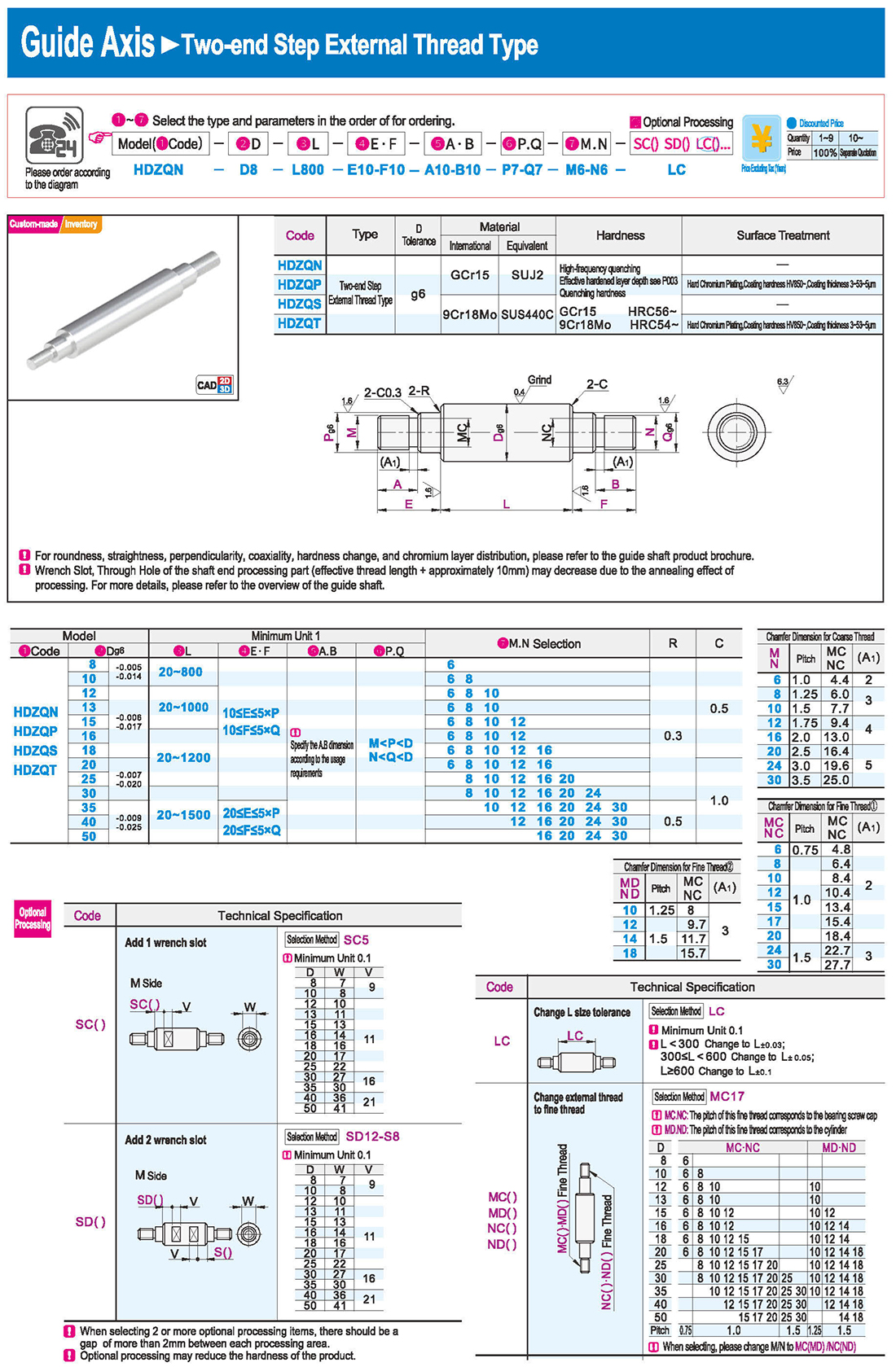
Optional processing may reduce the hardness of the product
One-end Step and One-end External Thread Type
One-end Step Internal Thread and One-end External Thread Type
Change external thread to fine thread
One-end Step External Thread Type
One-end Step External Thread and One-end Internal Thread Type
Chamfer Dimension for Coarse Thread
Chamfer Dimension for Fine Thread
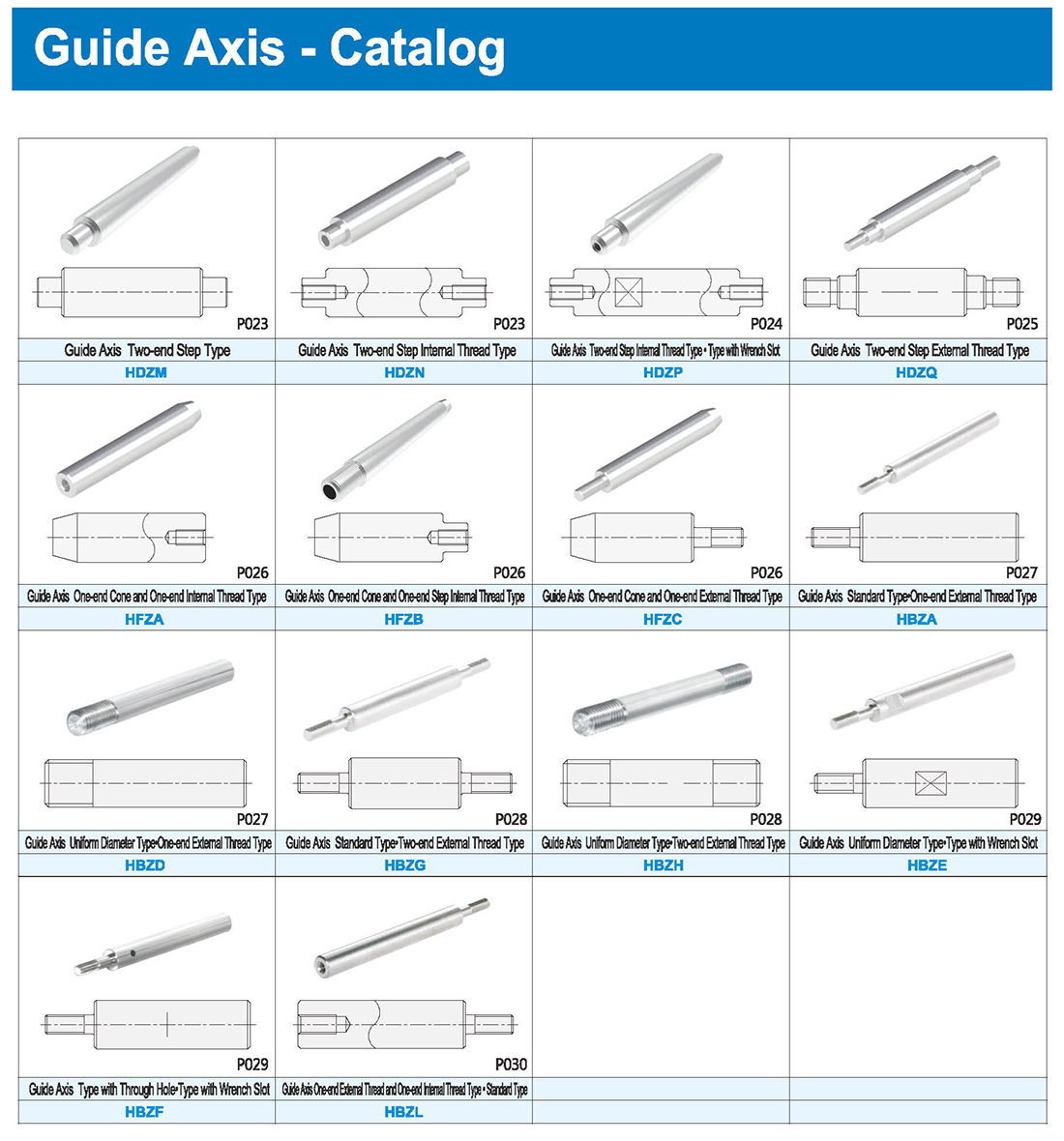
Two-end Step Type · Two-end Step Internal Thread Type
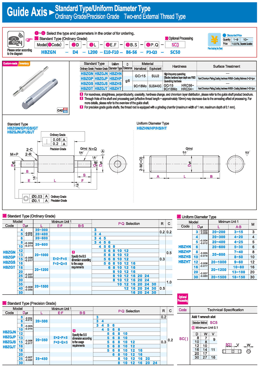
Two-end Step External Thread Type
One-end Cone and One-end Internal Thread Type · One-end Cone and One-end Step Internal Thread Type
One-end Cone and One-end External Thread Type
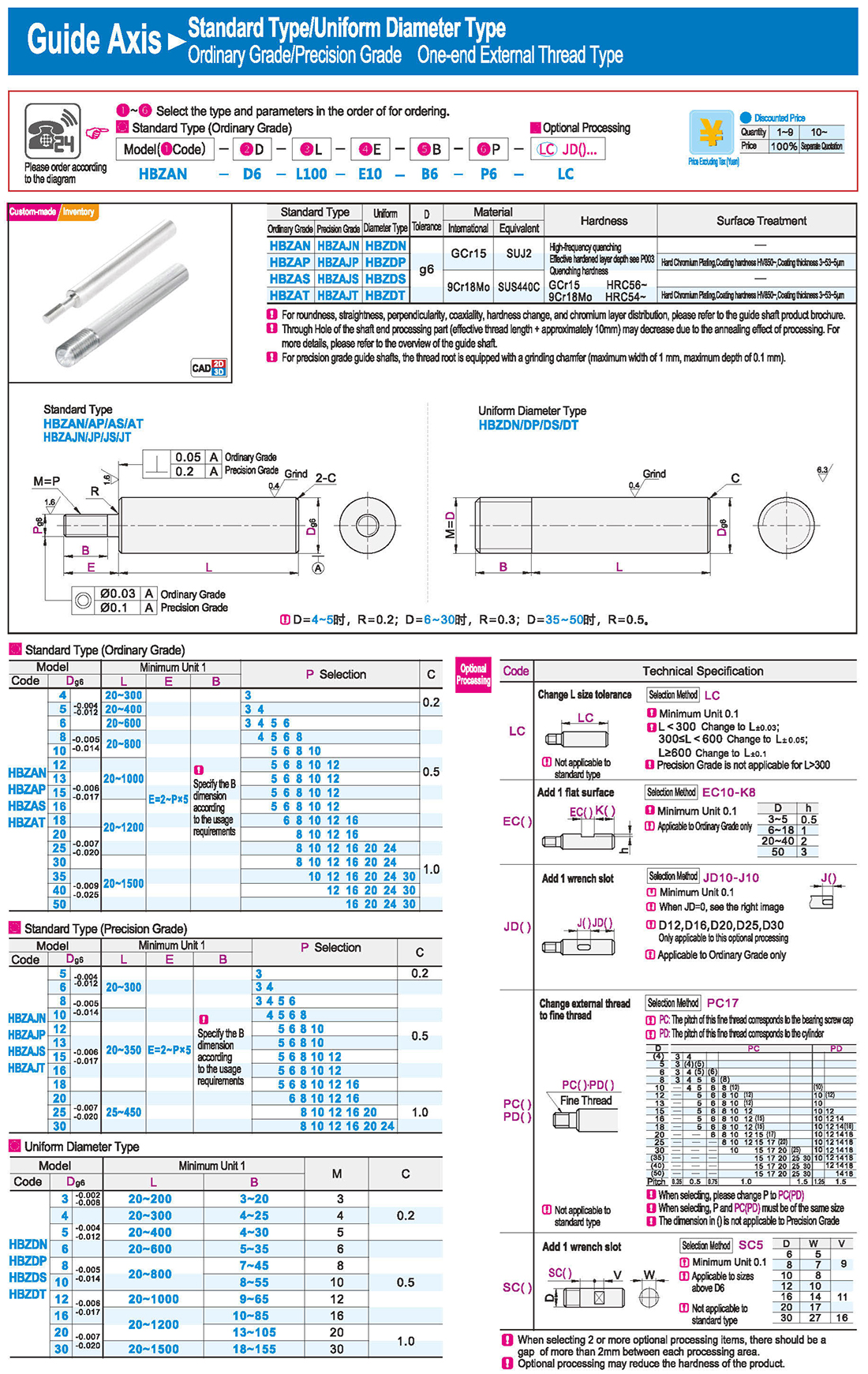
Uniform Diameter Type
Ordinary Grade/Precision Grade One-end External Thread Type
Type with Through Hole
One-end External Thread and One-end Internal Thread Type





 inglese
 russo
russo spagnolo
 italiano
 arabo
arabo coreano
 tedesco
 giapponese
 vietnamita
 turco
turco

 introduzione
 Tabella specifica
 scarica


