Smooth operation
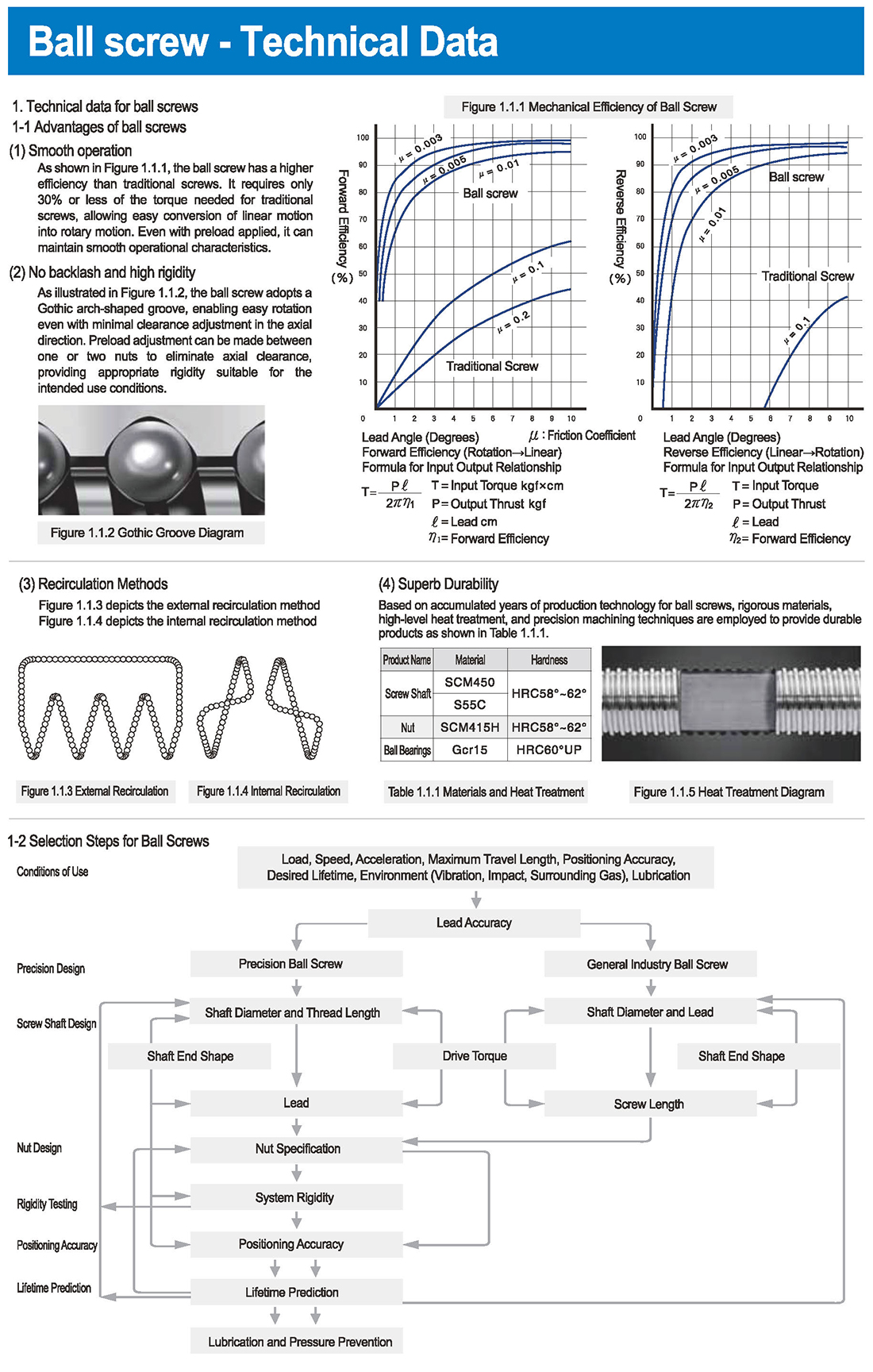
(1) As shown in Figure 1.1.1, the ball screw has a higher efficiency than traditional screws. It requires only 30% or less of the torque needed for traditional screws, allowing easy conversion of linear motion into rotary motion. Even with preload applied, it can maintain smooth operational characteristics.
(2) No backlash and high rigidity
As illustrated in Figure 1.1.2, the ball screw adopts a Gothic arch-shaped groove, enabling easy rotation even with minimal clearance adjustment in the axial direction. Preload adjustment can be made between one or two nuts to eliminate axial clearance, providing appropriate rigidity suitable for the intended use conditions.
1-1 Selection Steps for Ball Screws
Load, Speed, Acceleration, Maximum Travel Length, Positioning Accuracy, Desired Lifetime, Environment (Vibration, Impact, Surrounding Gas), Lubrication
Conditions of Use Precision Design Screw Shaft Design Nut Design Rigidity Testing
Lifetime Prediction Drive Torque Shaft End Shape Lead Accuracy
Precision Ball Screw Shaft Diameter and Thread Length Nut Specification System Rigidity Lubrication and Pressure Prevention
Drive Torque General Industry Ball Screw Shaft Diameter and Lead Screw Length Shaft End Shape
1-3-1 Lead Accuracy
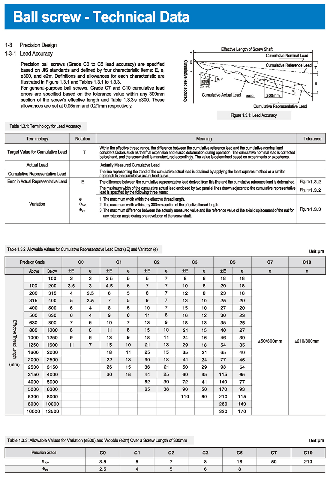
Precision ball screws (Grade C0 to C5 lead accuracy) are specified based on JIS standards and defined by four characteristic items: E, e, e300, and e2π. Definitions and allowances for each characteristic are illustrated in Figure 1.3.1 and Tables 1.3.1 to 1.3.3.
For general-purpose ball screws, Grade C7 and C10 cumulative lead errors are specified based on the tolerance value within any 300mm section of the screw’s effective length and Table 1.3.3’s e300. These allowances are set at 0.05mm and 0.21mm respectively.
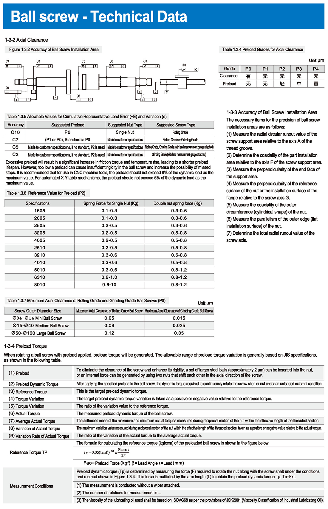
1-3-3 Accuracy of Ball Screw Installation Area
The necessary items for the precision of ball screw installation areas are as follows:
(1) Measure the radial circular runout value of the screw support area relative to the axis A of the thread groove.
(2) Determine the coaxiality of the part installation area relative to the axis F of the screw support area.
(3) Measure the perpendicularity of the end face of the support area.
(4) Measure the perpendicularity of the reference surface of the nut or the installation surface of the flange relative to the screw axis G.
(5) Measure the coaxiality of the outer circumference (cylindrical shape) of the nut.
(6) Measure the parallelism of the outer edge (flat installation surface) of the nut.
(7) Determine the total radial runout value of the screw axis.
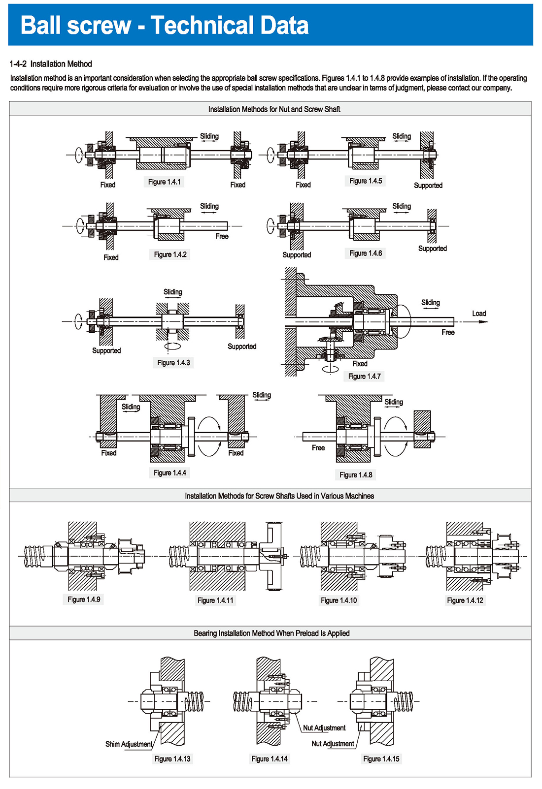
Installation Method
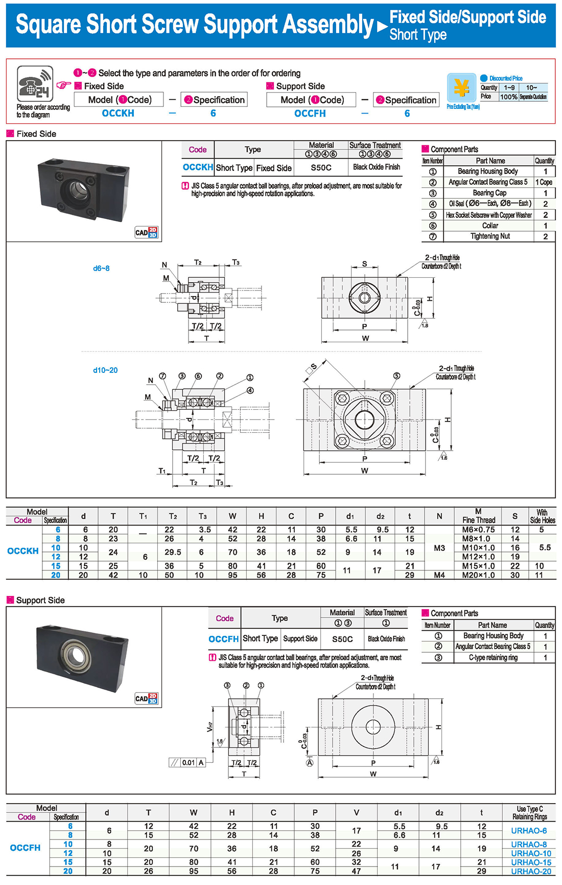
Installation method is an important consideration when selecting the appropriate ball screw specifications. Figures 1.4.1 to 1.4.8 provide examples of installation. If the operating conditions require more rigorous criteria for evaluation or involve the use of special installation methods that are unclear in terms of judgment, please contact our company.
Installation Methods for Nut and Screw Shaft Sliding Load Installation Methods for Screw Shafts Used in Various Machines
Bearing Installation Method When Preload Is Applied Nut Adjustment Shim Adjustment
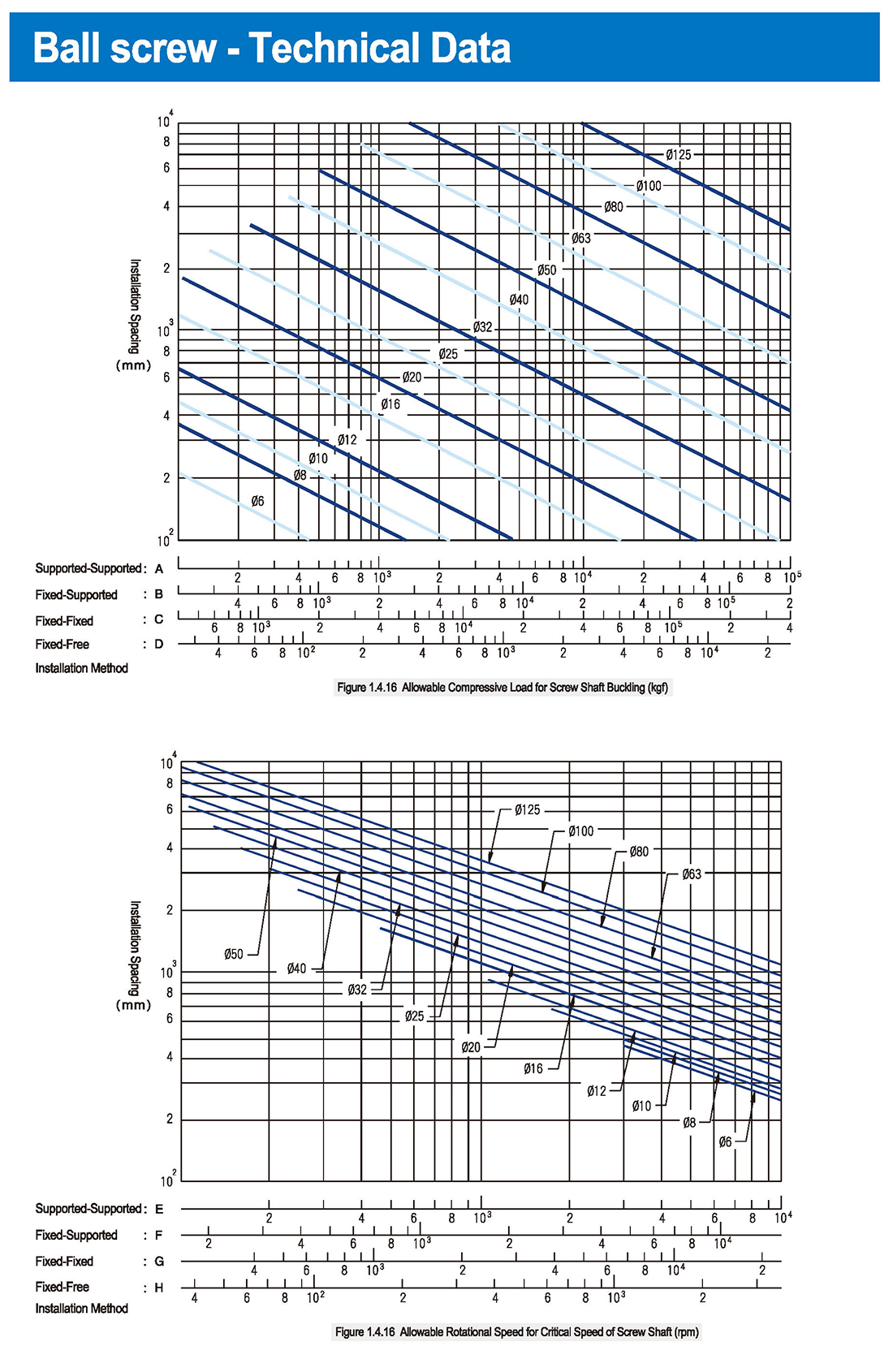
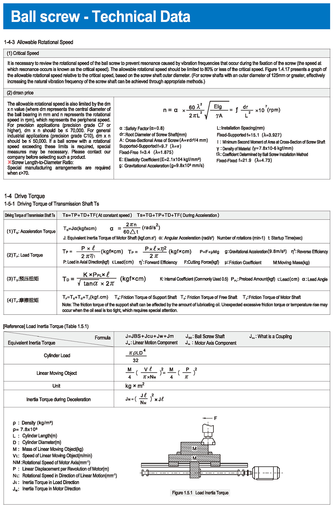
Allowable Compressive Load for Screw Shaft Buckling Allowable Rotational Speed for Critical Speed of Screw Shaft。
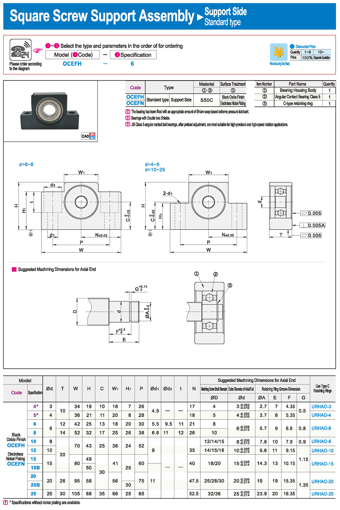

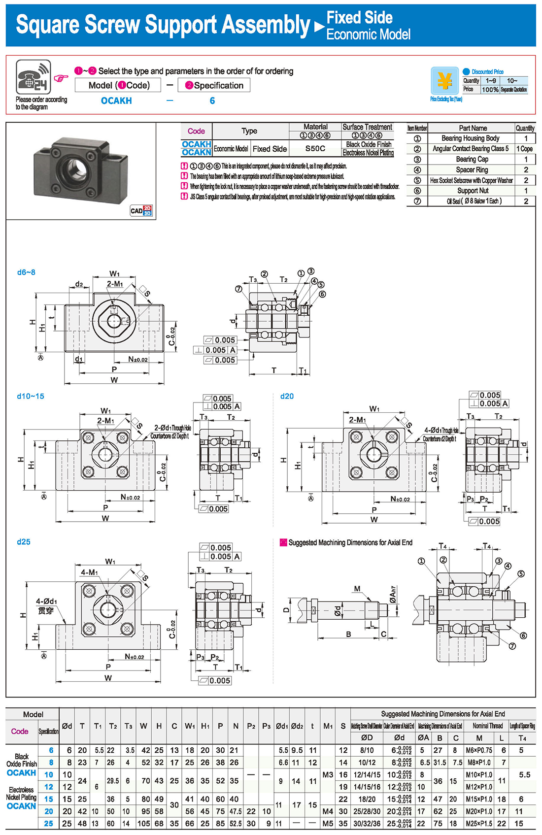
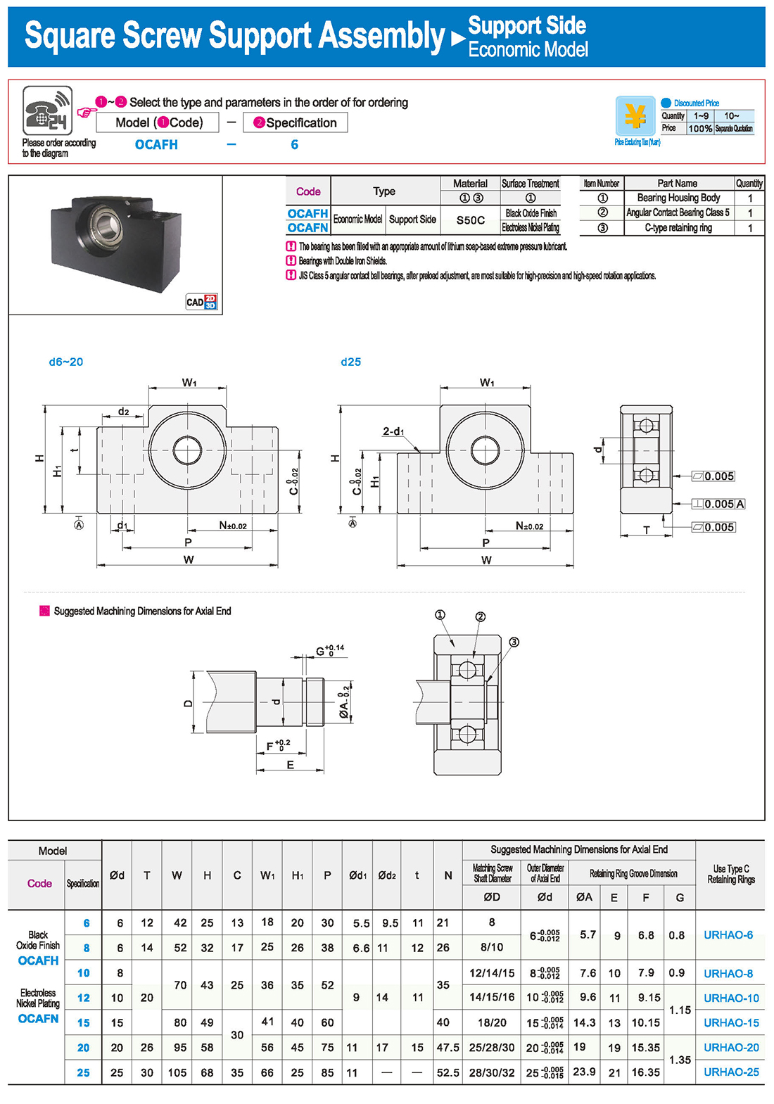

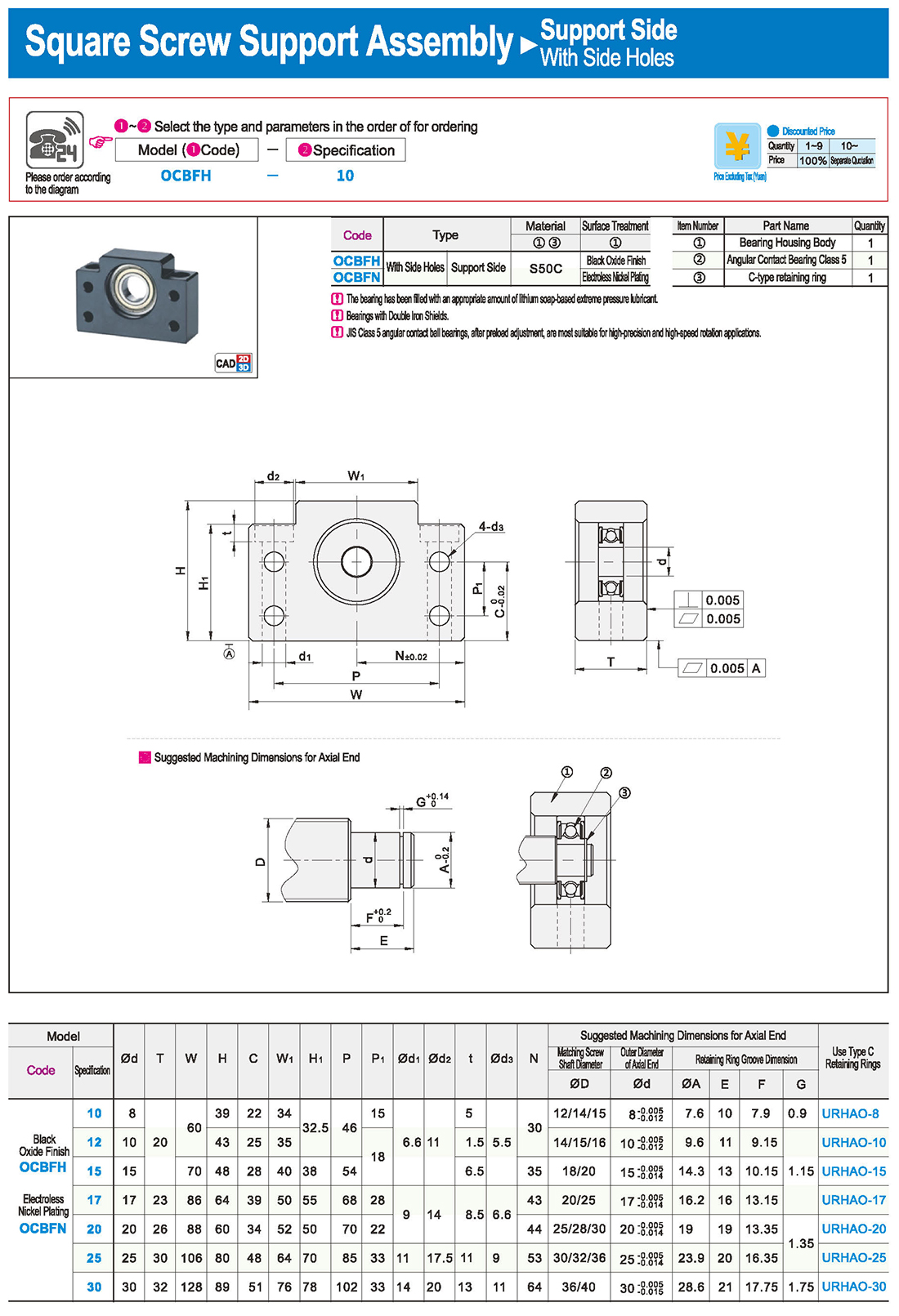
1-9 Precautions for the Use of Ball Screws
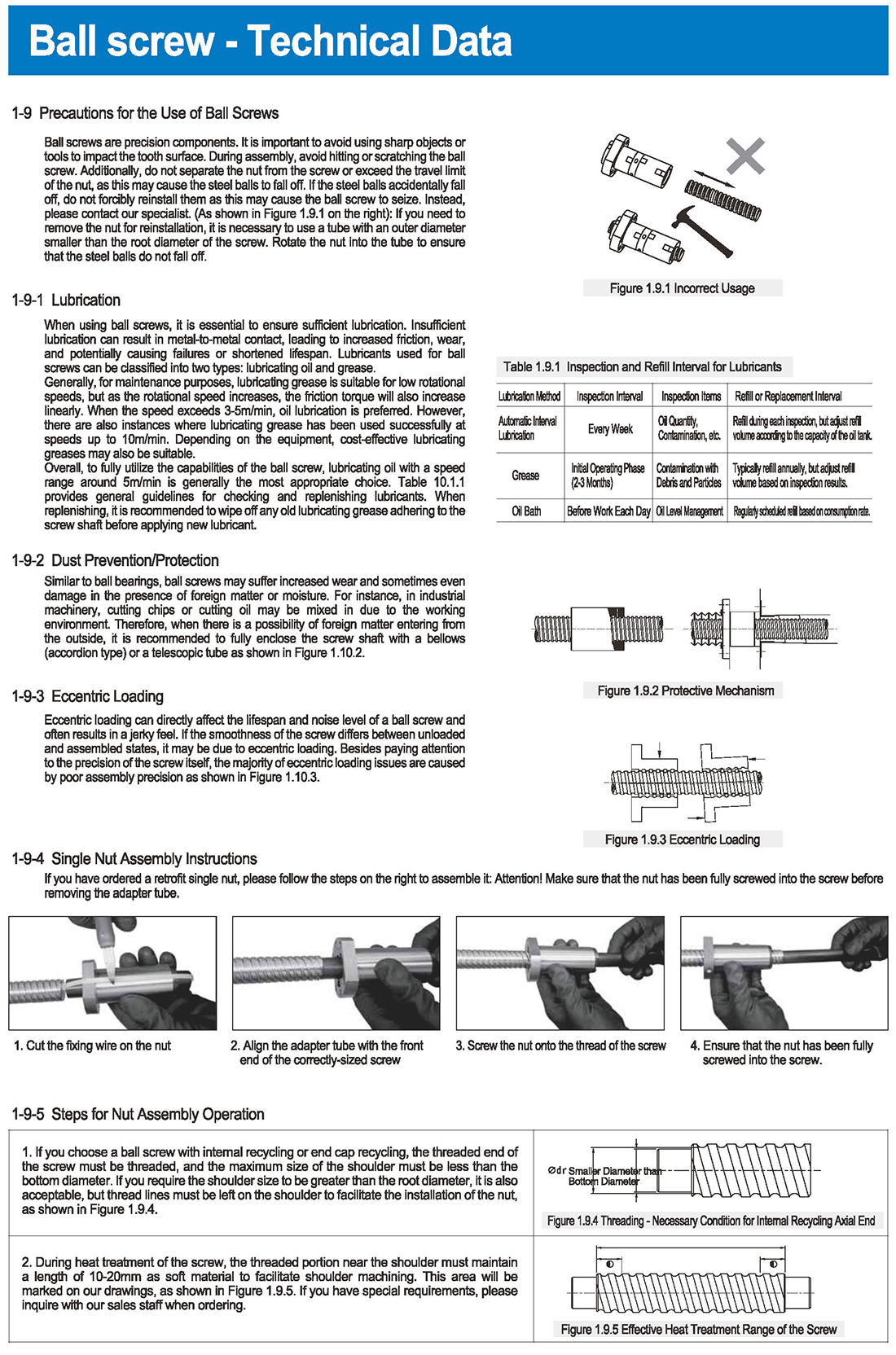
Ball screws are precision components. It is important to avoid using sharp objects or tools to impact the tooth surface. During assembly, avoid hitting or scratching the ball screw. Additionally, do not separate the nut from the screw or exceed the travel limit of the nut, as this may cause the steel balls to fall off. If the steel balls accidentally fall off, do not forcibly reinstall them as this may cause the ball screw to seize. Instead, please contact our specialist. (As shown in Figure 1.9.1 on the right): If you need to remove the nut for reinstallation, it is necessary to use a tube with an outer diameter smaller than the root diameter of the screw. Rotate the nut into the tube to ensure that the steel balls do not fall off.
1-9-1 Lubrication
When using ball screws, it is essential to ensure sufficient lubrication. Insufficient lubrication can result in metal-to-metal contact, leading to increased friction, wear, and potentially causing failures or shortened lifespan. Lubricants used for ball screws can be classified into two types: lubricating oil and grease.
Generally, for maintenance purposes, lubricating grease is suitable for low rotational speeds, but as the rotational speed increases, the friction torque will also increase linearly. When the speed exceeds 3-5m/min, oil lubrication is preferred. However, there are also instances where lubricating grease has been used successfully at speeds up to 10m/min. Depending on the equipment, cost-effective lubricating greases may also be suitable.
Overall, to fully utilize the capabilities of the ball screw, lubricating oil with a speed range around 5m/min is generally the most appropriate choice. Table 10.1.1 provides general guidelines for checking and replenishing lubricants. When replenishing, it is recommended to wipe off any old lubricating grease adhering to the screw shaft before applying new lubricant.
Inspection and Refill Interval for Lubricants
Lubrication Method | Inspection Interval | Inspection Items | Refill or Replacement Interval
Automatic Interval Lubrication | Every Week | Oil Quantity, Contamination, etc. | Refill during each inspection, but adjust refill volume according to the capacity of the oil tank.
Initial Operating Phase (2-3 Months) | Contamination with Debris and Particles | Typically refill annually, but adjust refill volume based on inspection results.
Oil Bath | Before Work Each Day | Oil Level Management | Regularly scheduled refill based on consumption rate.
2 Dust Prevention/Protection
Similar to ball bearings, ball screws may suffer increased wear and sometimes even damage in the presence of foreign matter or moisture. For instance, in industrial machinery, cutting chips or cutting oil may be mixed in due to the working environment. Therefore, when there is a possibility of foreign matter entering from the outside, it is recommended to fully enclose the screw shaft with a bellows (accordion type) or a telescopic tube as shown in Figure 1.10.2.
3 Eccentric Loading
Eccentric loading can directly affect the lifespan and noise level of a ball screw and often results in a jerky feel. If the smoothness of the screw differs between unloaded and assembled states, it may be due to eccentric loading. Besides paying attention to the precision of the screw itself, the majority of eccentric loading issues are caused by poor assembly precision as shown in Figure 1.10.3.


 inglese
 russo
russo spagnolo
 italiano
 arabo
arabo coreano
 tedesco
 giapponese
 vietnamita
 turco
turco
 introduzione
 Tabella specifica
 scarica